

Gear Reducer Selection Guide: Torque, Speed & Installation
Choosing the wrong reducer costs more than money — it causes downtime, accelerated wear, and premature failure. This guide walks through the five core steps every engineer needs to get selection right the first time.
I. Define Your Application Requirements First
Before touching any specification sheet, clarify the reducer's exact role in your equipment. Selection starts with requirements, not parameters.
Core Mission
A reducer serves two simultaneous functions in most applications: speed reduction and torque multiplication. Confirm which takes priority in your design.
Operating Environment
The environment dictates gearbox type, IP rating, materials, and service life. Define your conditions: temperature range, humidity, dust levels, corrosive exposure, and cleanliness requirements — before narrowing models.
Load Type
- Uniform Load — Fans, pumps, conveyor belts (constant speed). Standard selection criteria apply.
- Moderate Shock Load — Mixers, packaging machines (intermittent). Add margin.
- Heavy Shock Load — Crushers, stamping machines, excavator buckets. Prioritize impact resistance and apply a high service factor.
Work Schedule
Continuous 24-hour operation (S1) versus cyclic work-rest duty (S3, S5) directly affects thermal rating and calculated service life. Confirm duty cycle before sizing.
II. Calculate Core Parameters: Torque, Speed & Power
Motor Power (P₁) — kW
Your starting input value. Confirm rated power from the motor nameplate.
Reduction Ratio (i)
Determined by input speed (n₁) and required output speed (n₂), both in rpm:
Example: 1450 rpm input ÷ 145 rpm output = i = 10
Required Output Torque (T₂) — Nm
This is the most critical parameter. Use the standard formula:
(T in Nm, P in kW, n in rpm)
In practice, derive T₂ from load resistance measurements or empirical data for similar equipment, then divide by reduction ratio and efficiency.
Service Factor (fₛ)
Apply a service factor based on shock severity and required service life (typically 1.2–2.5+). Final selection torque:
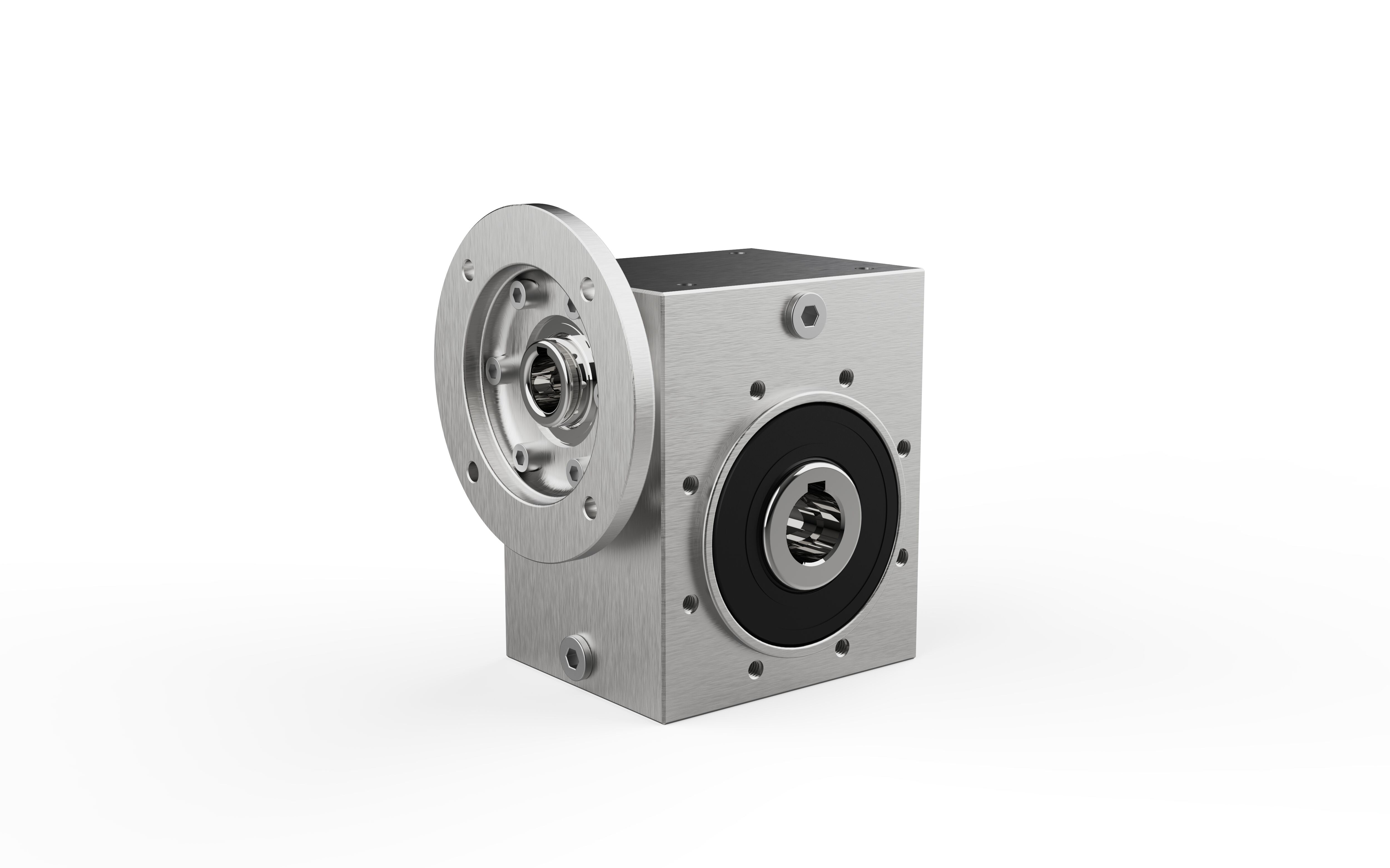
III. Match Installation Configuration to Your Layout
Output End Options
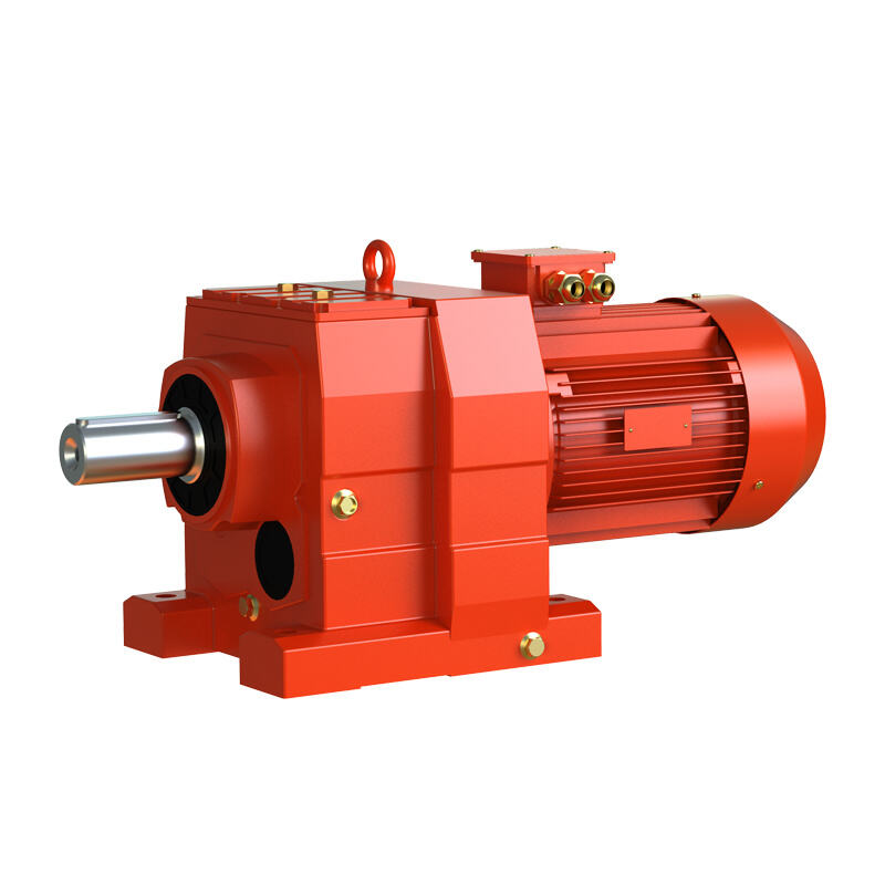
- Solid Shaft
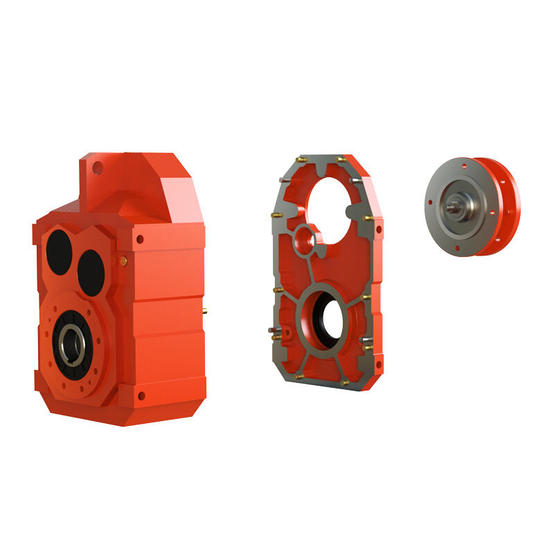
- Hollow Shaft
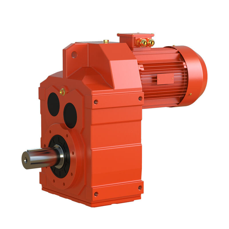
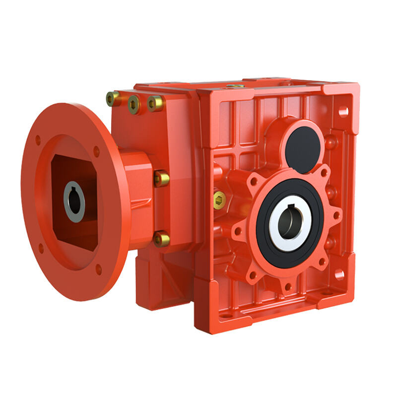
- Flange Output
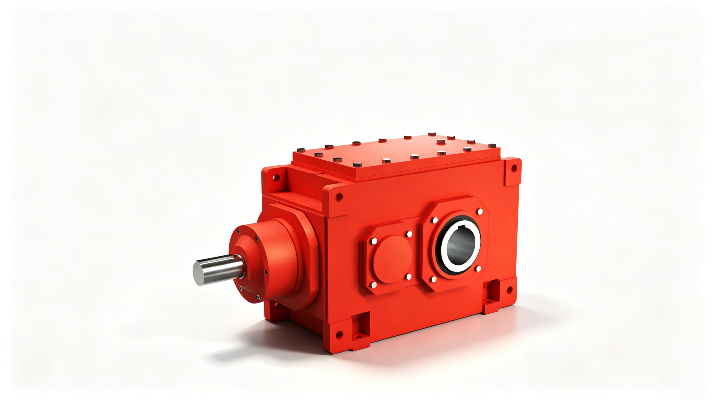
Input End Options
- Input Flange
- Input Shaft
Mounting Method
- Foot-Mounted — Base-bolted. Most common, highest stability.
- Flange-Mounted — Output or side flange mount. Compact and space-saving.
- Torque Arm Mounted — Required for medium-to-large gearboxes needing reaction torque absorption.
IV. Environmental & Efficiency Factors
IP Protection Rating
Dusty, wet, or washdown environments require elevated IP ratings. Define operating conditions before selecting housing material and sealing specifications.
Lubrication & Maintenance Life
- Maintenance-free grease life: Critical for reducers in difficult-to-access locations.
- Forced oil lubrication: Required for large or heavy-duty units with continuous high-load operation.

Operating Temperature Range
Cold storage or high-temperature metallurgical environments require materials and lubricants specifically rated for those conditions. Confirm the thermal operating range.
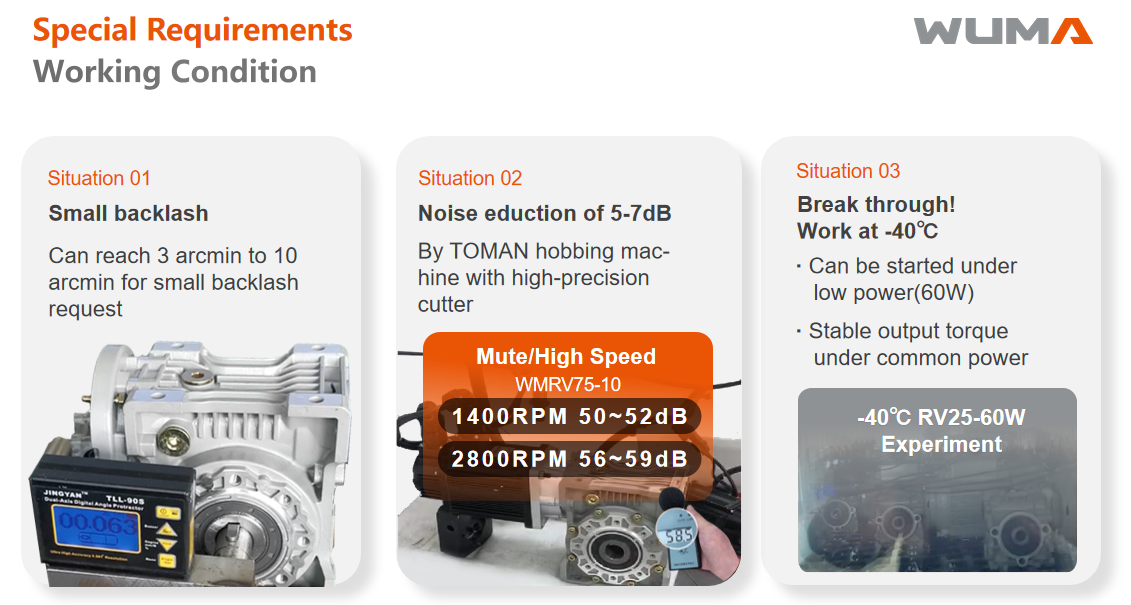
Noise Requirements
For noise-sensitive environments (medical, laboratory), helical, planetary, or worm gear reducers offer lower acoustic output.
Backlash Tolerance
Precision positioning systems (turntables, indexing equipment) require backlash below 1 arc-minute — select planetary or RV reducers. Standard conveyance applications tolerate >10 arc-minutes.
V. Common Selection Mistakes to Avoid
• Oversized: Unnecessary cost, weight, volume, and inertia.
• Undersized: Overheating, accelerated wear, tooth breakage. Balance reliability against cost.
Reducer selection comes down to five priorities: define requirements → calculate torque → choose the right type → confirm installation → assess the environment. Get these right and the correct model follows.
Need help selecting the right gear reducer for your application?
Contact Wuma Drive — our engineers will recommend the best-fit solution at no cost.
 Hot News