
 EN
EN

Direct answer: The service factor (SF) is the ratio of a gear reducer's rated output torque to the actual load torque — an engineering buffer for real-world operating uncertainties. Setting SF too low causes premature failure; setting it too high wastes budget and degrades system performance. The correct SF is the techno-economic balance point: sufficient to cover all operating condition variables, without unnecessary overengineering.
What Is the Service Factor and Why Does It Matter?
In gear reducer selection, the service factor (SF) — also known as the application factor or safety factor — is defined as:
A correctly specified SF ensures the reducer's rated capacity remains above the actual peak operating torque throughout its service life — accounting for variables that cannot be precisely quantified at the design stage: impact loads, start-stop cycling, inertial torque during acceleration, and environmental degradation of effective capacity.
In practice, SF selection tends toward two damaging extremes. Neither is acceptable in professional engineering:
| Extreme | Cause | Consequence |
|---|---|---|
| SF too low | Minimizing upfront purchase cost | Premature gear fatigue, unplanned downtime, replacement costs that exceed original savings |
| SF too high | Risk aversion, blanket over-engineering | 30–50% cost premium, larger housing, higher energy loss, degraded servo dynamic performance |
I. Under-Selection: Short-Term Savings, Long-Term Losses
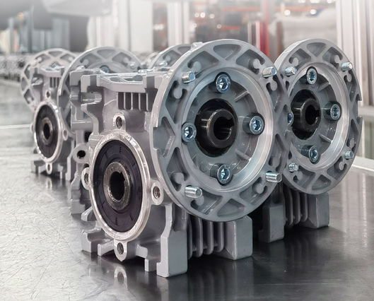
When SF is set below the actual operating requirement, the gear reducer runs near its fatigue limit for extended periods. The resulting failures are not sudden quality defects — they are cumulative damage from underestimating operating condition variables at the selection stage.
Typical Failure Modes from Under-Selection
- Tooth surface pitting — fatigue micro-cracks under repeated contact stress below rated capacity
- Scuffing (adhesive wear) — oil film breakdown at tooth contact under peak impact loads
- Tooth breakage — single-event overload fracture when inertial torque during starts exceeds rated torque
- Premature bearing failure — radial load exceeds bearing capacity when load distribution shifts due to gear wear
The True Cost of Under-Selection
| Cost Category | Description |
|---|---|
| Production downtime | Unplanned shutdowns stop the entire production line — downtime cost typically exceeds the gearbox replacement cost many times over |
| Parts replacement | Gear set, bearings, seals, and connected shaft components often require simultaneous replacement |
| Labor and commissioning | Maintenance labor, re-alignment, and recommissioning add significant indirect cost |
| Accelerated wear cycle | An under-selected replacement unit installed in the same application fails again — the root cause is the SF, not the product quality |
II. Over-Selection: Hidden Waste and Performance Degradation
Over-selection is more easily overlooked than under-selection precisely because it does not cause immediate equipment failure. However, the economic and technical penalties accumulate silently across the full equipment lifespan.
| Impact Area | Effect of Over-Selection |
|---|---|
| Purchase cost | One frame size larger typically adds 30–50% to the gearbox purchase price |
| Structural cost | Larger housing requires heavier mounting frames, larger couplings, and increased structural material — all sized to the gearbox, not the load |
| Energy losses | Greater rotational inertia and higher no-load losses generate continuous additional energy consumption throughout the equipment lifetime |
| Servo system performance | Elevated inertia ratio degrades servo response speed and positioning accuracy — particularly damaging in precision motion control and robotics applications |
III. How to Determine the Correct Service Factor: Four Evaluation Dimensions
A correct SF is not a single number — it is the output of evaluating four interdependent dimensions simultaneously. Addressing any one dimension in isolation leads to either under- or over-selection.
Dimension 1: Duty Cycle Type
Different IEC duty cycle designations correspond to different thermal equilibrium conditions and fatigue load spectra — and require different SF starting points:
| Duty Cycle | Description | SF Starting Point |
|---|---|---|
| S1 | Continuous operation — constant load, no rest periods | 1.0 – 1.25 |
| S3 / S4 | Intermittent — periodic work-rest cycles | 1.25 – 1.75 |
| S5 / S6 | Intermittent with braking — includes deceleration torque | 1.5 – 2.5+ |
Dimension 2: Start-Stop Frequency and Dynamic Load
Every start cycle generates inertial torque that can significantly exceed steady-state running torque — especially in high-inertia loads. The higher the start-stop frequency, the greater the contribution of dynamic torque to the effective load spectrum. Applications with more than 10 starts per hour should be evaluated with a dedicated dynamic load analysis rather than relying on catalog SF tables.
Dimension 3: Operating Environment
Environmental conditions directly affect the gear reducer's effective capacity relative to its rated specification:
- High ambient temperature — reduces lubricant viscosity, weakens oil film, and lowers the effective thermal rating
- Continuous vibration or shock — accelerates bearing fatigue and increases dynamic tooth load beyond the calculated static value
- Contamination or humidity — compromises lubrication integrity over time, requiring a higher SF margin to compensate for degraded tribological performance
Dimension 4: Reliability Requirements and Maintenance Interval
The acceptable level of failure probability and the cost of failure drive the final SF calibration:
- Safety-critical applications (lifting, personnel-carrying) — require the highest SF margins regardless of calculated static load
- Long maintenance intervals (remote installations, continuous process plants) — a higher SF offsets the inability to perform frequent inspections or early interventions
- Standard industrial automation — SF can be tightly optimized where maintenance access is routine and load profiles are well-characterized
Service Factor Reference Guide by Application Type
| Application Type | Load Character | Typical SF Range |
|---|---|---|
| Fans, pumps, conveyors (constant speed) | Uniform — steady state, no impact | 1.0 – 1.25 |
| Mixers, packaging machines | Moderate shock — intermittent, variable load | 1.25 – 1.75 |
| Crushers, stamping machines, excavators | Heavy shock — high impact, inertia-dominated | 1.75 – 2.5+ |
| Servo drives, precision positioning | Dynamic — inertia matching is critical; SF must balance safety and response | 1.0 – 1.5 (verify inertia ratio) |
| Lifting equipment, hoists | Safety-critical — failure consequence is highest | 2.0 – 3.0+ |
FAQ: Gear Reducer Service Factor
What is the service factor (SF) in gear reducer selection?
SF is the ratio of the reducer's rated output torque to the actual required load torque. It compensates for real-world operating uncertainties — impact loads, start-stop cycles, inertial torque, and environmental degradation — that cannot be precisely quantified at the design stage.
What happens if the service factor is too low?
The reducer operates near its fatigue limit continuously. Typical results: tooth surface pitting, scuffing, tooth breakage, and premature bearing failure — followed by unplanned production downtime whose cost far exceeds the initial savings on gearbox price.
What happens if the service factor is too high?
Purchase cost increases 30–50%, housing size grows requiring heavier mounting structures, no-load energy losses accumulate across the equipment lifetime, and in servo applications, the inertia ratio imbalance degrades dynamic response and positioning accuracy.
What is a typical service factor for continuous-duty industrial reducers?
Uniform load / S1 continuous: SF 1.0–1.25. Moderate shock (mixers, packaging): SF 1.25–1.75. Heavy shock (crushers, stamping): SF 1.75–2.5+. Lifting / safety-critical: SF 2.0–3.0+. Always verify against the actual duty cycle, start-stop frequency, and environment.
How do I determine the correct service factor?
Evaluate four dimensions together: (1) duty cycle type (S1/S3/S5); (2) start-stop frequency and inertial torque contribution; (3) operating environment (temperature, vibration, contamination); (4) reliability requirements and maintenance interval. The correct SF balances all four — not just the static load torque.
The service factor is not a safety margin to pad conservatively — it is the result of a structured engineering analysis. Accurate SF specification is what separates a gearbox that performs reliably for its full design life from one that fails early or wastes budget from day one.
Need help determining the correct service factor for your application?
Submit Your Application Parameters — Get a Free SF Selection Review from Wuma Drive →
 Hot News