
When selecting a gearbox for a mechanical drive system, installation configuration is a key factor. Beyond the structural difference between parallel-shaft and right-angle-shaft gearboxes, you also need to decide between horizontal and vertical mounting. These two choices together determine how the entire drive system occupies three-dimensional space — and understanding their impact is essential for efficient layout in tight installations.
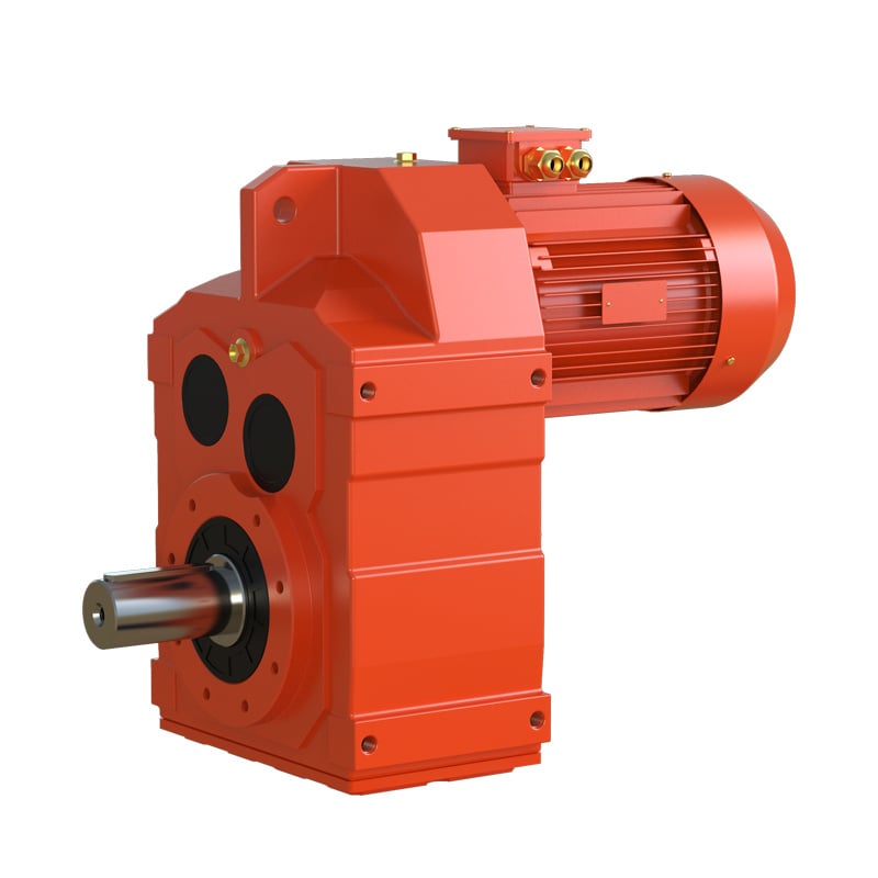
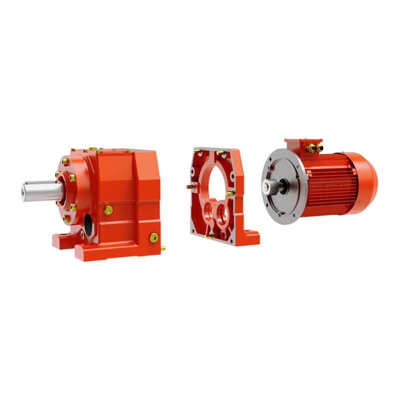
Parallel-shaft gearboxes have input and output shafts running in the same direction. This creates a straight-line drive train: motor, gearbox, and driven machine all align along one axis, forming an in-line arrangement. The setup is simple, easy to align, and leaves plenty of room for maintenance. The trade-off is that it demands enough axial space. For long conveyors or large mixers, however, this in-line layout actually matches the equipment's natural orientation, so no space is wasted.
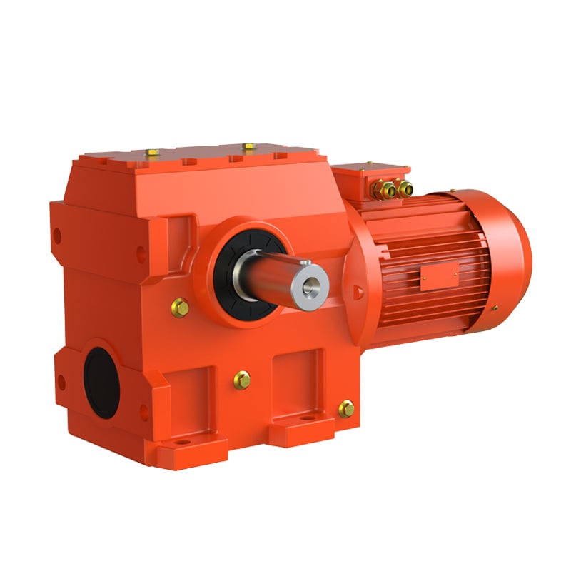
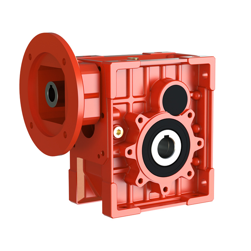
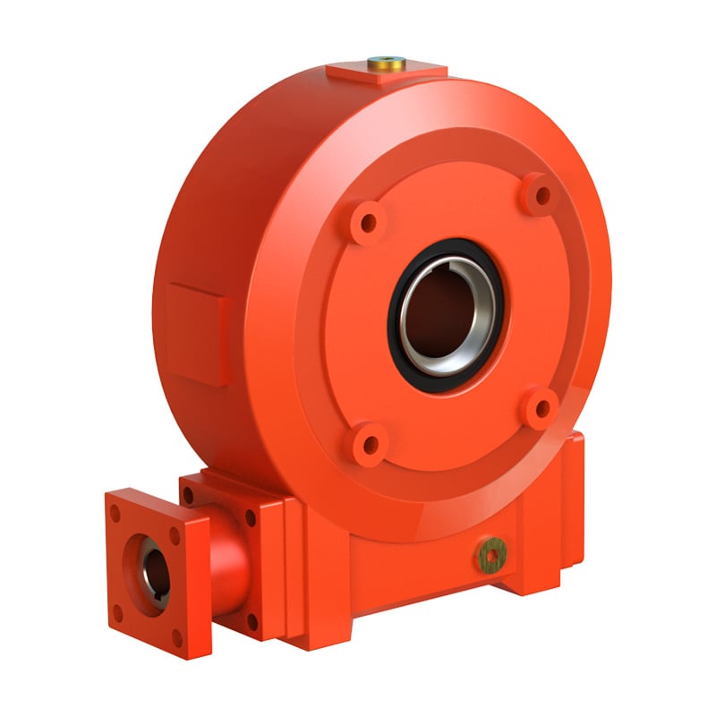
Right-angle-shaft gearboxes have input and output shafts at 90°, typically using bevel gears or a worm-gear pair to redirect the power. The key benefit is that the motor can mount perpendicular to the driven machine, effectively "folding" the drive chain and saving a lot of floor space. In compact installations — tank-top agitators, crane travel drives, packaging machinery — this L-shaped layout often becomes the only practical option. The motor can hang to the side or sit on top without interfering with other components.
Beyond shaft direction, reducers also come in horizontal (foot-mounted) and vertical (flange-mounted) configurations. Horizontal reducers have their output shaft pointing sideways, a base for floor mounting, a low center of gravity, and good stability. This is the most common form and suits the majority of industrial applications. Vertical reducers have their output shaft pointing straight up or down, and the housing normally bolts to the equipment via a flange. This configuration is designed specifically for vertical-drive applications such as upright mixers or certain hoisting mechanisms.
Combining shaft direction with mounting position gives several specific configurations: parallel-shaft horizontal, parallel-shaft vertical, right-angle horizontal, and right-angle vertical. Each has a different effect on the overall equipment design. Two common examples are worth looking at in detail.
Parallel-shaft horizontal is the classic choice. Motor and reducer sit side by side on a flat surface, connected to the working machine through a coupling or belt drive. Alignment of all shaft centerlines is critical. The advantages are straightforward maintenance and good heat dissipation, making it well suited for heavy-duty continuous operation. In mining conveyors and large fans, this is the standard arrangement.
Right-angle vertical is the go-to for vertical-drive applications. The motor mounts on top of the reducer, and the output shaft points straight down. This layout is widely used in vertical agitators, reactors, and crystallizers. Its biggest strength is a small footprint — multiple agitators can be packed closely together on a tank roof. The challenge, however, is lubrication and sealing. In vertical mounting, the bearing and gear lubrication conditions are entirely different from horizontal mounting, requiring dedicated oil-circuit design and careful oil-level control.
1.Map the available space first. A parallel-shaft in-line layout needs room along the axial direction; a right-angle L-shaped layout needs lateral clearance; a vertical layout needs height. Comparing these dimensions against the reducer's envelope dimensions is usually enough to narrow down feasible options early on.
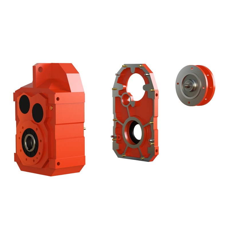
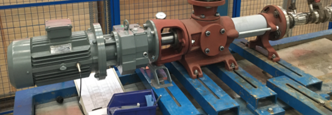
2.Check the interface and connection method. The driven machine has an exposed input shaft, a hollow-bore right-angle reducer that slips directly onto it is the simplest solution. If using a flexible coupling, a parallel-shaft horizontal gearbox is more straightforward. When space is not a constraint, always favor the simpler and more efficient parallel-shaft option.
3.Consider lubrication and cooling. Horizontal reducers have the most mature lubrication practice — oil level is easy to set, and the housing surface provides good cooling. Vertical reducers need extra provisions such as forced lubrication or specially designed splash circuits. In high-temperature or continuous heavy-load conditions, horizontal mounting is generally the safer choice. High-power vertical reducers often require a separate oil tank.
4.Leave room for maintenance. After installation, there must be accessible clearance for routine inspection, oil changes, and bolt tightening. The position of the motor terminal box and the location of lifting lugs also need to be factored into the layout. A layout that looks compact on paper can quietly raise long-term operating costs if it makes routine maintenance difficult.
5.Account for load direction and structural rigidity. The output shaft of a gearbox carries both radial and axial forces from the working machine. In horizontal mounting, these forces are handled by internal bearings and transferred to the foundation through the housing. In vertical mounting, the gearbox acts as a cantilevered structure, placing higher demands on flange strength and connection stiffness.
The goal is never to push one parameter to its limit, but to achieve efficient, maintainable power transmission within a finite three-dimensional space. A well-thought-out layout makes the drive system feel like a natural part of the machine — and that is what keeps the whole production line running smoothly over the long term.
 Hot News
2026-06-29
2026-06-24
2026-06-24
2026-06-23
2026-06-18
2026-05-22
Welcome to Wuma , a manufacturer committed to developing and manufacturing various types of gear reducers and gearmotors for the field of gear transmission.
No. 10, Xiangcun Industrial Zone, Dongyuan Town, Qingtian County, Lishui City, Zhejiang, China
Copyright © Zhejiang Wuma Drive Co., Ltd All Rights Reserved Privacy Policy Blog