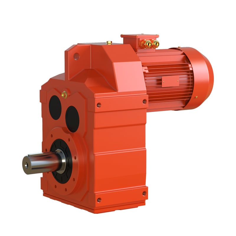

Gearboxes are mechanical transmission systems designed to reduce speed and increase the torque, and are key components in industrial automation and robotics. Their operating characteristics under no-load and loaded conditions are drastically different, exhibiting distinct mechanical, thermal, and electrical properties.
I. No-Load Operation
No-load operation occurs when the output shaft of the gearbox is disconnected from any external resistance or torque-demanding mechanism. Under this condition:
Force Environment: The speed reducer experiences only internal resistive forces—namely, gear meshing friction, bearing rolling resistance, and lubricant churning losses. Noexternal torque opposes motion.
Output State: The output flange remains unconnected; thus, no reaction torque is generated at the output end.
Performance Profile: Input power consumption is minimal, limited to overcoming internal losses. Rotational speed remains stable and closely aligned with the theoretical gear ratio, unaffected by load-induced slip or dynamic disturbances.
Note: No-load operation is not “idle” but rather a state of controlled internal dissipation—essential for initial system validation and control tuning.
II. Loaded Operation
Loaded operation begins when an external mechanism is coupled to the output shaft, imposing torque and resistance that the reducer must transmit. In this state:
Force Environment: The reducer has to now overcome both internal friction and the external load torque, creating a dual-energy-dissipation pathway.
Load Dynamics: The magnitude, direction, and variability of the load may fluctuate dynamically with process conditions (e.g., conveyor jams, robotic pick-and-place cycles), inducing transient stress peaks.
System Response: Input power scales nonlinearly with load; efficiency peaks at 70–90% of rated torque; thermal rise accelerates due to compounded heat sources (gear friction, windage, motor copper losses).
Critical Insight: Loaded operation is the design intent of the reducer. Its performance under real-world load defines reliability, lifespan, and system integration success.
III. Excessive No-Load Current: Root Cause Analysis
An elevated no-load current is not caused by insufficient load—it is a symptom of internal degradation or system fault:
Bearing Wear: Increased rolling resistance raises mechanical load on the motor, forcing higher current draw.
Gear Surface Degradation: Micro-pitting or misalignment increases meshing friction, elevating torque demand.
Lubricant Degradation: Oxidized or contaminated oil increases churning losses and viscous drag.
Electrical Faults: Shorted motor windings, insulation breakdown, or phase imbalance cause magnetic asymmetry and current distortion.
Supply Voltage Drop: Undervoltage forces the motor to draw more current to maintain speed, mimicking mechanical overload.
Misconception Alert: Attributing high no-load current to “low load” reflects a fundamental misunderstanding of motor mechanics. The motor does not “compensate” for lack of load—it responds to increased internal resistance.
V. Conclusion
The distinction between no-load and loaded operation is not merely operational—it is diagnostic. No-load conditions serve as a baseline for health assessment; loaded conditions reveal true performance limits. Understanding this duality enables predictive maintenance, precise control tuning, and failure root-cause analysis.
 Hot News
2026-06-29
2026-06-24
2026-06-24
2026-06-23
2026-06-18
2026-05-22
Welcome to Wuma , a manufacturer committed to developing and manufacturing various types of gear reducers and gearmotors for the field of gear transmission.
No. 10, Xiangcun Industrial Zone, Dongyuan Town, Qingtian County, Lishui City, Zhejiang, China
Copyright © Zhejiang Wuma Drive Co., Ltd All Rights Reserved Privacy Policy Blog