
 EN
EN

Direct answer: A worm gear reducer self-locks when its lead angle (λ) is smaller than the equivalent friction angle (ρ) of the worm-and-wheel material pair — making it physically impossible for the output shaft to back-drive the input. This is not an unconditional property: it can be compromised by multi-start worm design, over-lubrication, high temperatures, or sustained vibration. Reliable self-locking requires precise engineering control over geometry, materials, and operating conditions.
What Is Worm Gear Self-Locking?
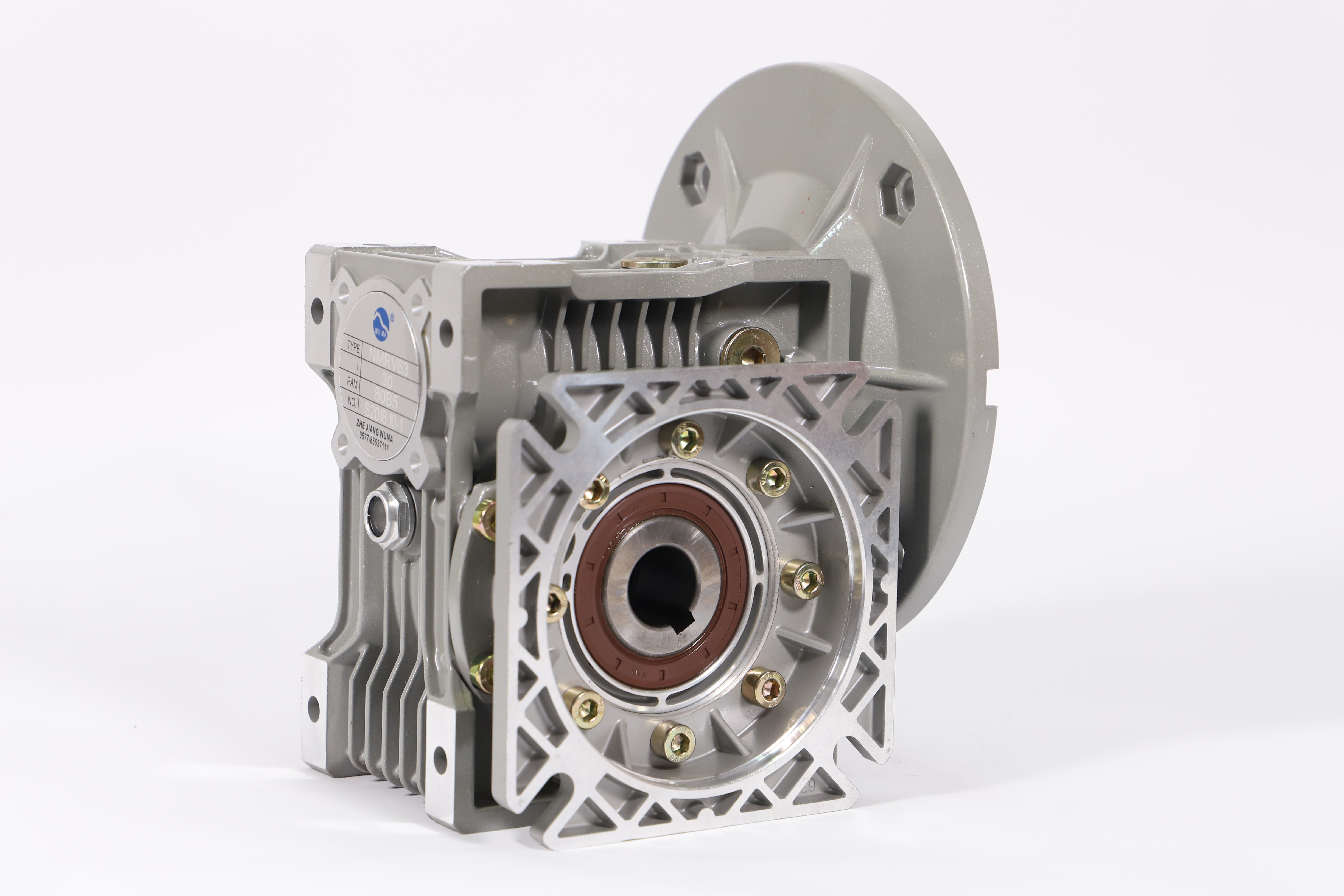
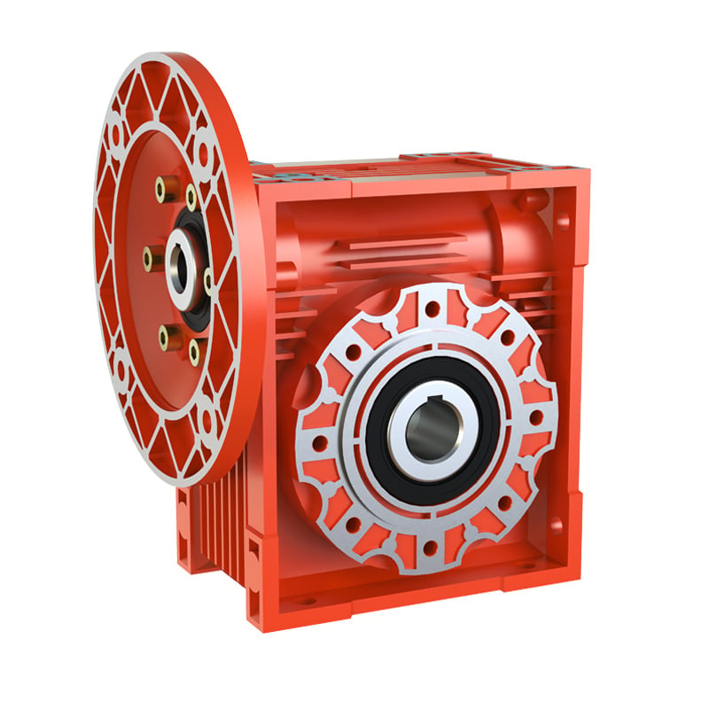
Self-locking is the inherent ability of a WMRV worm gearbox to prevent the output shaft (worm wheel) from reverse-driving the input shaft (worm) under load — without any external brake or locking device. When engaged, the output shaft is mechanically held in position the moment driving force is removed.
This property makes worm gear reducers the preferred choice in applications where gravity or external loads must be held statically — including vertical conveyors, lifting platforms, valve actuators, and positioning stages.
| Feature | Worm Gear with Self-Locking | Helical / Planetary (No Self-Locking) |
|---|---|---|
| Back-driving Risk | None (when λ < ρ) | High — requires external brake |
| Load Holding | Mechanical — no power required | Requires powered brake or motor holding torque |
| Typical Application | Lifts, valve actuators, positioning tables | High-speed, high-efficiency continuous drives |
| Additional Safety Device | Often not required (low-risk loads) | Brake required for any load-holding duty |
How Worm Gear Self-Locking Works
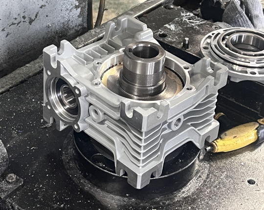
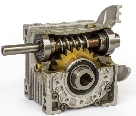
The meshing of the worm's helical surface against the worm wheel teeth is mechanically equivalent to an inclined-plane transmission model. Two angular quantities govern whether the system self-locks:
- Lead angle (λ) — the helix angle of the worm thread, determined by the number of starts and the worm pitch diameter. A single-start worm has a small λ; multi-start worms have a larger λ.
- Equivalent friction angle (ρ) — derived from the friction coefficient (μ) of the worm-wheel material pair (typically hardened steel worm against tin bronze wheel): ρ = arctan(μ). For steel-on-bronze under normal lubrication, ρ ≈ 5°–7°.
Self-locking condition: λ < ρ. When this is satisfied, the axial force generated by any output-side load cannot overcome static friction on the worm thread surface — reverse rotation is geometrically blocked without any additional mechanism.
| Worm Starts | Typical Lead Angle (λ) | Reduction Ratio Range | Self-Locking? |
|---|---|---|---|
| 1 (single-start) | 2° – 6° | i = 20 – 100 | Yes ✓ |
| 2 (double-start) | 6° – 12° | i = 10 – 20 | Marginal ⚠ |
| 4+ (multi-start) | > 12° | i = 5 – 10 | No ✗ |
Lead Angle Threshold: The Critical Design Parameter
The boundary condition λ = ρ is the exact self-locking threshold. Below it, the system self-locks. Above it, back-driving becomes possible. Engineers must account for the full range of operating variables that shift this boundary in real conditions:
| Variable | Effect on ρ (Friction Angle) | Impact on Self-Locking |
|---|---|---|
| Steel worm + tin bronze wheel | μ ≈ 0.08–0.12 → ρ ≈ 5°–7° | Reliable self-locking zone |
| Over-lubrication (excessive oil) | μ drops → ρ decreases | Self-locking margin reduced |
| High operating temperature (>80°C) | Viscosity drops → oil film weakens → μ falls | Critical threshold approached |
| Surface wear (long service) | Surface finish changes → μ shifts unpredictably | Periodic inspection required |
| Sustained vibration / impact load | Disrupts static friction equilibrium dynamically | Momentary reverse slip possible |
Limitations: When Self-Locking Cannot Be Relied Upon
Self-locking is a conditional property — not an absolute guarantee. Three categories of conditions can compromise or eliminate it:
1. Geometric Conditions (Design-Stage)
Multi-start worms selected for higher efficiency have lead angles that exceed the friction angle threshold. Any worm with λ ≥ ρ is inherently non-self-locking regardless of operating conditions. This is a fixed design-stage constraint that cannot be corrected by lubrication or material changes.
2. Material & Lubrication Conditions
Low-friction material combinations (e.g. steel-on-steel instead of steel-on-bronze) or over-lubrication during assembly and maintenance reduce the actual friction coefficient, pushing ρ below λ and eliminating the self-locking margin. Lubricant specification and fill quantity must be controlled to manufacturer specification.
3. Operating Environment Conditions
High temperatures reduce lubricant viscosity and alter the boundary lubrication state of the friction pair. Thermal expansion of the worm and wheel changes meshing clearances, redistributing contact pressure. Continuous external vibration or shock loading can dynamically disrupt static friction equilibrium, causing momentary reverse sliding even when the static condition λ < ρ is satisfied at rest.
How Wuma Drive Engineers Reliable Self-Locking
Self-locking reliability is an engineering outcome — not a material property. Wuma Drive applies the following controls across the full production and validation process to ensure consistent self-locking performance in every WMRV worm gearbox shipped:
| Control Area | Wuma Drive Practice | Purpose |
|---|---|---|
| Geometry Design | Lead angle calculated with safety margin below ρ across full operating temperature range | Guarantees λ < ρ under worst-case thermal conditions |
| Material Certification | Tin bronze worm wheels with batch friction coefficient verification | Ensures consistent ρ across production batches |
| Dynamic Simulation | Start/stop inertia, vibration loads, and thermal cycling modeled in selection validation | Identifies self-locking margin degradation under real duty cycles |
| Lubrication Control | Factory-specified oil grade and fill volume per frame size; documented in product manual | Prevents over-lubrication from reducing effective friction coefficient |
| 100% Load Testing | Every unit undergoes output-side load test to verify no back-drive under rated torque | Ships only units with confirmed self-locking performance |
FAQ: Worm Gear Self-Locking
What is the self-locking function of a worm gear reducer?
Self-locking means the output shaft cannot back-drive the input when external load is applied. It occurs when the worm's lead angle (λ) is less than the equivalent friction angle (ρ) of the material pair — making reverse rotation geometrically impossible without a power source.
What lead angle is required for reliable self-locking?
Self-locking is reliable when λ < 6° (approximately). In practice, single-start worms at reduction ratios i ≥ 20 consistently achieve this. Multi-start worms at low ratios (i < 10) generally cannot self-lock.
Can self-locking fail in a worm gear reducer?
Yes — under three main conditions: multi-start worm geometry (λ ≥ ρ by design); over-lubrication or low-friction materials reducing effective μ; and high temperatures or sustained vibration dynamically disrupting the friction balance at the contact surface.
Is worm gear self-locking reliable enough to replace a mechanical brake?
For non-critical static holding (valve actuators, horizontal conveyors), self-locking is typically sufficient. For safety-critical vertical lifting or personnel-carrying equipment, a dedicated mechanical brake is mandatory — self-locking serves only as a supplementary feature.
Which Wuma Drive gearboxes have verified self-locking?
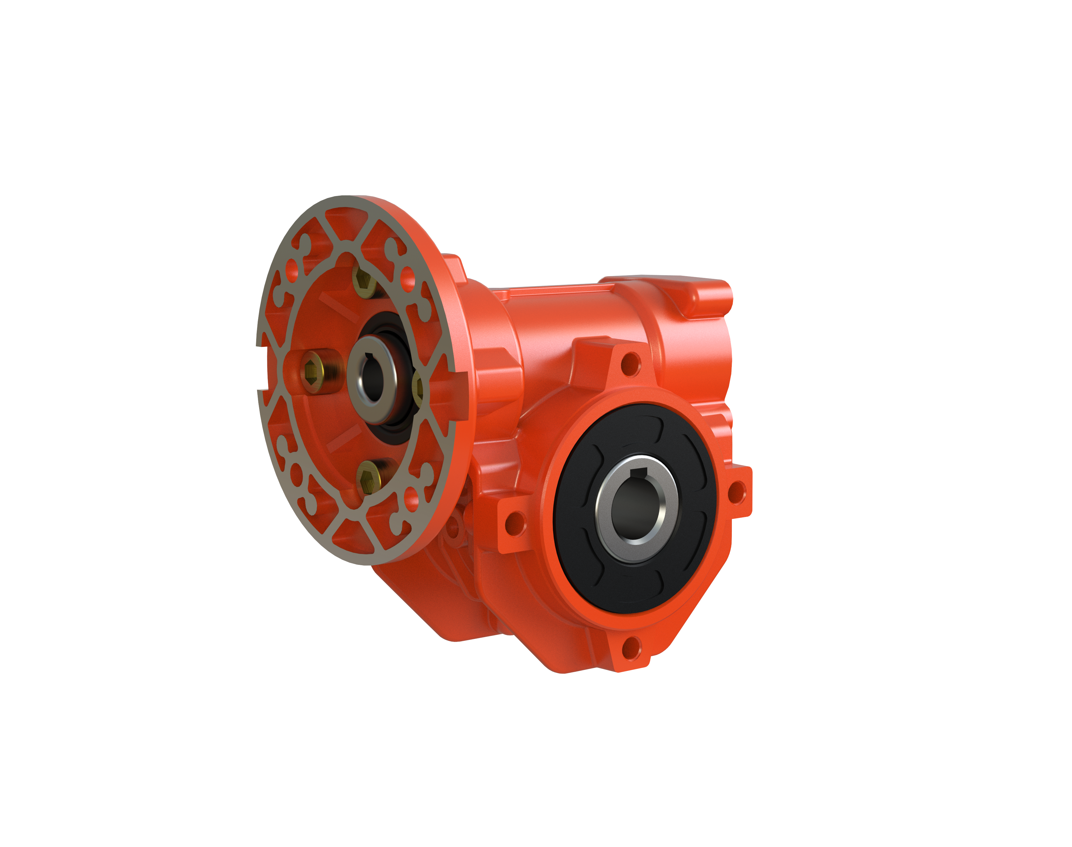
The WMRV worm gearbox (single-start worm, i = 20–100) is factory-tested for self-locking performance. Every unit undergoes output-side load verification before shipment.
Self-locking is the result of materials science, tribology, precision manufacturing, and operational condition management working in concert. It is not a passive feature — it is an engineered outcome that must be specified, controlled, and validated for each application.
Need to verify self-locking for your specific duty cycle, reduction ratio, or operating environment?
Submit Your Application Parameters — Get a Free Self-Locking Validation from Wuma Drive →
 Hot News