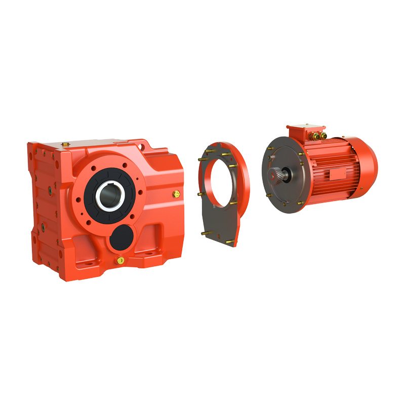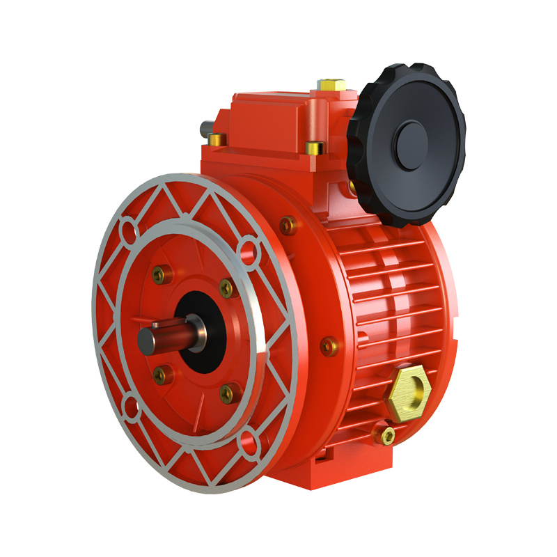

The mechanical planetary cone disk variator is a sophisticated continuously variable transmission device. It can achieve continuous and smooth changes in output speed within a predetermined range by mechanical adjustment while maintaining a constant input speed. Its core principle does not rely on traditional gear ratio changes, but rather on the continuous change of contact radius in friction transmission.
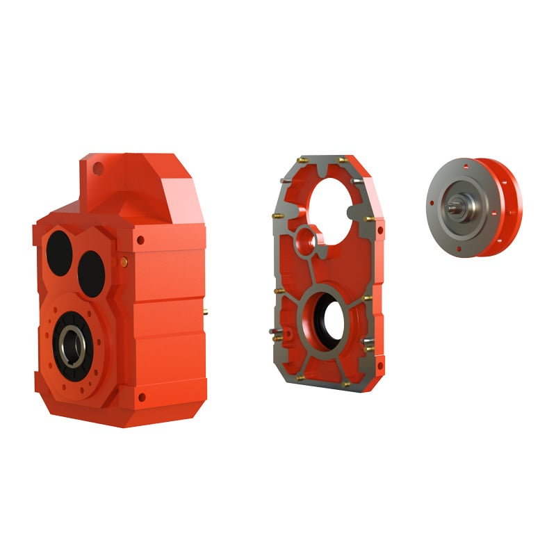
The main structure of this transmission includes an input shaft, an output shaft, and a planetary cone disk mechanism. The input shaft is connected to a driving sun cone disk. The sun cone disk typically has a concave conical friction surface. Around the sun cone disk, several planetary conical gears are evenly distributed. These planetary cone disk are double-conical in shape, with their two conical surfaces contacting the inner conical surface of the sun cone disk and the inner conical surface of an axially movable pressure ring (or output ring), respectively. Supported by a cage or planet carrier, the planetary conical gears can rotate on their own axis and also revolve within the cavity formed by the sun cone disk and the pressure ring.
The speed change process is a precise mechanical coordination action. When we need to change the output speed, we drive the speed regulating screw to rotate via an external handwheel or speed regulating mechanism. This screw pushes the speed regulating nut to produce axial displacement. The movement of the nut, through a set of thrust bearings or linkage mechanisms, ultimately transmits and changes the angular position of the speed regulating cam or swashplate. This change in cam angle forces all planetary conical gears to tilt synchronously, that is, change the angle between their axes and the axis of the sun cone disk.
The change in the tilt angle of the planetary conical gears is the physical key to its speed change. When the planetary cone disk is at a specific tilt angle, the effective radius of its contact point with the sun cone disk is fixed. The radius of this contact point from the center of rotation of the sun cone disk constitutes the input radius of the transmission. Simultaneously, the radius of the contact point between the planetary cone disk and the outer pressure ring constitutes the output radius of the transmission. This is equivalent to continuously changing the ratio of the transmission radii of the driving side (sun cone disk) to the driven side (pressure ring), i.e., the transmission ratio.
Specifically, when the adjusting mechanism tilts the planetary cone gear in a certain direction, its contact point with the sun cone disk moves towards the larger end of the sun cone disk (increases the input radius), while its contact point with the pressure ring moves towards the smaller end of the pressure ring (decreases the output radius). According to the transmission ratio formula (output speed/input speed ≈ input radius/output radius), the transmission ratio increases, and the output speed decreases. Conversely, when the planetary cone gear tilts in the opposite direction, the input radius decreases while the output radius increases, the transmission ratio decreases, and the output speed increases. Throughout the adjustment process, the power transmission path is continuous: the input shaft drives the sun cone disk to rotate, which in turn drives the planetary cone gear to rotate via friction. The planetary cone gear then drives the pressure ring to rotate via friction, and the pressure ring ultimately transmits power to the output shaft.
When using this type of speed changer, operating procedures must be strictly followed to ensure its lifespan. First, overloading is absolutely prohibited. Overloading will immediately cause severe slippage, and the instantaneous high temperature may burn the friction surfaces of the conical disc and conical wheel, leading to permanent damage. The load must always be below its rated torque value. Second, speed adjustment must be performed while the machine is running. Speed adjustment operations must be performed while the input shaft is rotating. Forcibly turning the speed adjustment handwheel while the machine is stopped will severely wear or even jam the planetary conical wheel adjustment mechanism, causing equipment failure. Adjustments should be made slowly and evenly by turning the handwheel. Third, ensure adequate and proper lubrication. The manufacturer-specified special lubricating oil must be used. This lubricating oil not only lubricates the bearings and gears, but its specific coefficient of friction is also crucial for ensuring the stability of the torque transmitted by the friction pairs. Regularly check the oil level and change the oil according to the prescribed cycle to maintain its lubrication and cooling performance. Fourth, pay attention to operation monitoring and daily maintenance. During operation, listen for any abnormal noises and monitor whether the gearbox temperature is within the normal range. Regularly check whether all fasteners are loose. For equipment that operates for a long time, regularly check the wear of the planetary conical gears and friction discs according to the maintenance manual, and replace worn parts in a timely manner.
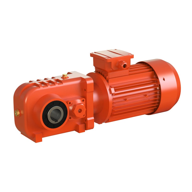
In summary, the mechanical planetary conical disc variator achieves stepless speed change by precisely changing the tilt angle of the planetary conical gears, thereby continuously changing the effective contact radius of the friction drive. It is a classic mechanism suitable for medium to low power applications where high smoothness of speed regulation is required. Only by deeply understanding the principles of its friction drive and geometric speed change, and strictly adhering to the requirements for load, speed regulation, and lubrication, can users ensure its reliable operation and achieve optimal performance.
 Hot News
2026-06-29
2026-06-24
2026-06-24
2026-06-23
2026-06-18
2026-05-22
Welcome to Wuma , a manufacturer committed to developing and manufacturing various types of gear reducers and gearmotors for the field of gear transmission.
No. 10, Xiangcun Industrial Zone, Dongyuan Town, Qingtian County, Lishui City, Zhejiang, China
Copyright © Zhejiang Wuma Drive Co., Ltd All Rights Reserved Privacy Policy Blog