
 EN
EN
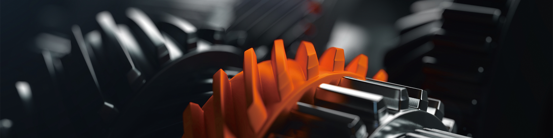
إجابة مباشرة: تتداخل التروس الحلزونية تدريجيًّا عبر أسنانها المائلة، مما يحافظ على تلامس عدة أسنان في وقتٍ واحد. ويؤدي هذا إلى القضاء على التصادم المفاجئ الناتج عن تداخل التروس المستقيمة — ما يقلل الضوضاء، ويوزع الحمل على مساحة تلامس أكبر، ويطيل عمر التروس. يستخدم كل علبة تروس حلزونية من سلسلة ووما درايف (WK / WR / WF / WS) تقنية التروس الحلزونية كمعيار افتراضي. وبذلك تحقِّق كفاءة نقل تبلغ ٩٤–٩٨٪ في التطبيقات الصناعية.
ما الذي يميِّز التروس الحلزونية عن التروس المستقيمة؟
يبدأ الاختلاف عند لحظة تداخل الأسنان. للتروس المستقيمة أسنانٌ مستقيمة موازية لمحور العمود. — وعندما تتقابل سنّان من التروس المستقيمة، فإنها تتداخل فجأةً عبر عرض السن بالكامل في وقتٍ واحد، كأن حافتين مستويتين تتصادمان بقوة. ويُنتج هذا التصادم الكامل عبر العرض ضوضاءً واهتزازاتٍ وإجهاداتٍ مركَّزة عند جذر السن.
أما التروس الحلزونية فلها أسنانٌ مقطوعة بزاويةٍ بالنسبة لمحور العمود. عند دوران التروس، يبدأ الاتصال بين الأسنان عند حافة واحدة ثم ينتقل تدريجيًّا عبر سطح السن — وهي عملية اشتباك دوَّار تدريجي تلغي التصادم المفاجئ. والنتيجة: تسليم عزم أكثر سلاسة، وضوضاء أقل، وإجهاد أقل بكثير على أي سنٍّ وحيد.
| الممتلكات | تروس مسننة | عتبة حلزونية |
|---|---|---|
| اتجاه الأسنان | مستقيم — موازٍ لمحور العمود | مائل — مقطوع بزاوية لولبية (عادةً ما تكون بين ١٥° و٢٥°) |
| نوع الاشتباك | مفاجئ — حيث يتلامس عرض السن بالكامل دفعة واحدة | تدريجي — حيث ينتقل التلامس عبر سطح السن |
| نسبة التلامس | منخفضة (عادةً ما تكون بين ١,٢ و١,٥ أسنان في حالة الاشتباك) | مرتفعة (عادةً ما تكون بين ٢,٠ و٣,٠+ أسنان في حالة الاشتباك) |
| مستوى الضوضاء | عالية — ضوضاء ذات تأثير كبير عند كل تداخل للأسنان | منخفضة — تماس سلس تدريجي |
| اهتزاز | عالية — أحمال صدم دورية | منخفضة — مشاركة مستمرة في التحميل |
| سعة التحميل | أقل — تركّز الإجهاد على عدد أقل من الأسنان | أعلى — توزيع الحمل عبر عدة أسنان |
| كفاءة النقل | 90–94% | 94–98% |
| دفع محوري | لا شيء | موجود — يُدار بواسطة محامل الدفع |
| تعقيد التصنيع | بسيطة — تكلفة أدوات أقل | متوسطة — تتطلب تحكّمًا دقيقًا في زاوية اللولب |
| التكلفة النسبية | منخفض | متوسط |
لماذا نسبة التلامس هي مؤشر الأداء الرئيسي
نسبة التلامس هي متوسط عدد أسنان التروس المتلامسة في نفس الوقت أثناء الدوران. تعني نسبة تلامس أعلى أن المزيد من الأسنان تشارك في تحمل الحمل المنقول في أي لحظة — مما يقلل بشكل مباشر من الإجهاد لكل سن، ويقلل الضوضاء، ويزيد من عمر التعب.
تبلغ نسبة التلامس في التروس الأسطوانية عادةً 1.2–1.5. وهذا يعني أنه خلال أجزاء كبيرة من كل دورة دوران، يحمل زوج واحد من الأسنان الحمل بالكامل — وهو ما يؤدي إلى تركيز الإجهاد والصدمات التأثيرية.
تبلغ نسبة التلامس في التروس الحلزونية 2.0 فأعلى. في أي لحظة أثناء الدوران، يشارك زوجان من الأسنان أو أكثر في تحمل الحمل في نفس الوقت. الانتقال بين أزواج الأسنان يكون سلساً وليس مفاجئاً، مما يحافظ على توصيل عزم الدوران الثابت ويقضي على الصدمة الدورية التي تسبب الضوضاء والتآكل المتسارع في محركات التروس الأسطوانية.
القيود المفروضة على القوة المحورية — وكيف يتم التغلب عليها هندسيًّا
تتميز التروس الحلزونية بعيبٍ جوهري واحد: فهندسة الأسنان المائلة تُولِّد مركبة قوة محورية على طول العمود بالإضافة إلى القوة المماسية المحركة. وإذا لم تُدار هذه القوة المحورية بشكلٍ مناسب، فقد تؤدي إلى إزاحة العمود، وحدوث تحميل غير منتظم على وجه الترس، وتسريع اهتراء المحامل.
يتعامل مهندسو شركة ووما درايف مع هذه المشكلة من خلال اختيار المحامل بدقة عالية وتحديد مواضعها بدقة. تحمل المحامل ذات التلامس الزاوي أو المحامل المخروطية المزدوجة عند طرفي العمود الحمل المحوري بالكامل، مما يحوّل ما كان ليكون عيبًا هيكليًّا إلى معامل تصميمي مُدارٍ بالكامل. والنتيجة هي توزيع متساوٍ للإجهادات عبر كامل سطح الأسنان وازدياد الاستقرار الهيكلي — دون أي تنازل عن سعة التحميل أو الكفاءة.
نهج هندسي بديل تُستخدمه بعض التصاميم عالية التحميل هو الترس العظمي (ذو الأسنان الحلزونية المزدوجة) — وهو عبارة عن مجموعتين من التروس الحلزونية المتعاكسة على جسم ترس واحد، حيث تلغي قوى الدفع المحوري المتبادلة بينهما بعضها البعض. وهذا يؤدي إلى إلغاء الأحمال المحورية تمامًا، لكنه يتطلب تعقيدًا تصنيعيًّا أعلى.
متى تختار التروس الحلزونية مقابل التروس المستقيمة؟
التروس المستقيمة ليست أدنى شأناً بطبيعتها — بل هي الخيار الأمثل في ظروف محددة. ويتوقف القرار على السرعة ودرجة التحمل للضوضاء والحمل والميزانية:
| الحالة | اختر الترس المستقيم | اختر الترس الحلزوني |
|---|---|---|
| سرعة التشغيل | سرعة منخفضة، وتشغيل متقطع | متوسط إلى عالي السرعة، تشغيل مستمر |
| متطلبات الضوضاء | الضوضاء مقبولة (في الهواء الطلق، الآلات النائية) | يتطلب ضوضاء منخفضة (الصناعات الغذائية، الصيدلانية، داخل المباني) |
| مستوى التحميل | حمل خفيف إلى متوسط | حمل متوسط إلى ثقيل، وكثافة عزم دوران عالية |
| تحمل الحمل المحوري | غير مسموح بأي حمل محوري على العمود | يتم إدارة الحمل المحوري بواسطة تصميم التحميل |
| منخفض التكلفة | أدنى تكلفة أولية هي الأولوية | خفض التكلفة الإجمالية للملكية على مدى عمر الخدمة |
| أولوية عمر الخدمة | دورة استبدال مقبولة | أقصى طول ممكن للعمر الافتراضي، وأدنى حد ممكن للصيانة |
سلسلة علب التروس الحلزونية من شركة ووما درايف: WK / WR / WF / WS
تستخدم جميع علب تروس ووما درايف الحلزونية مجموعات تروس حلزونية مصقولة بدقة كمعيار — وهي مصممة لتوفير كفاءة انتقال تتراوح بين ٩٤٪ و٩٨٪، ومستوى منخفض من الضوضاء، وعمر خدمة طويل دون الحاجة إلى صيانة في التطبيقات الصناعية الشديدة التطلب.
| السلسلة | التكوين | نطاق العزم | أفضل استخدام |
|---|---|---|---|
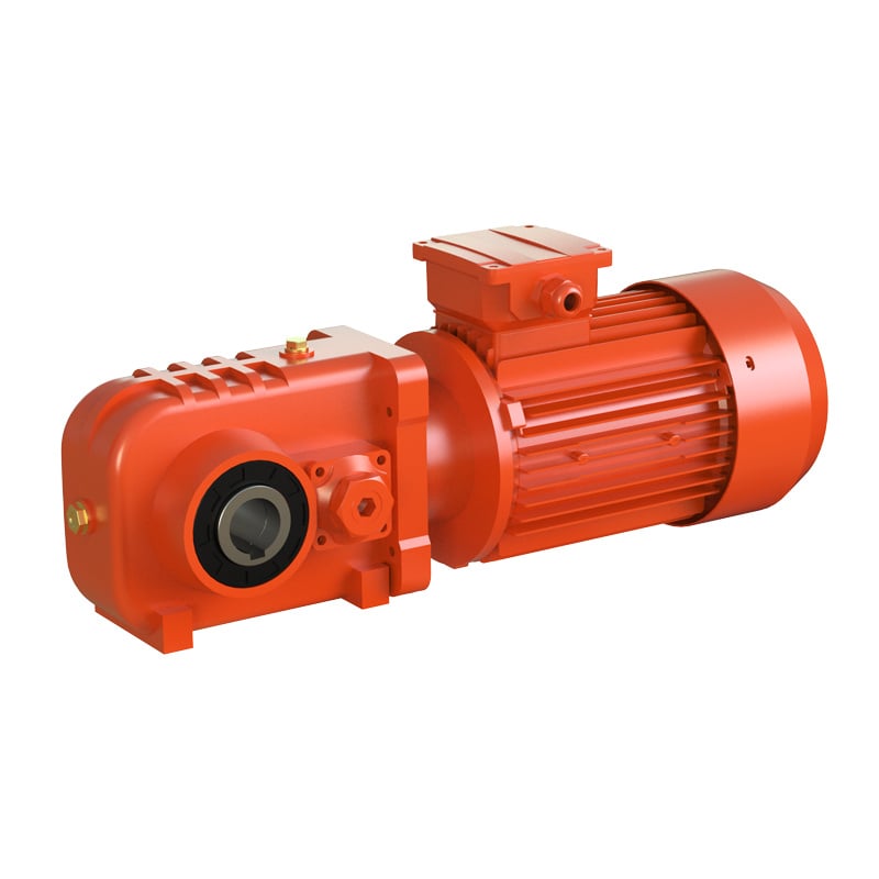
| سلسلة WK | محرك مائل-حلزوني بزاوية ٩٠ درجة | ٨٠–٥٠٬٠٠٠ نيوتن.متر | التعدين، والطيران والفضاء، والصناعات الدوائية، ومحركات الزوايا اليمنى المدمجة |
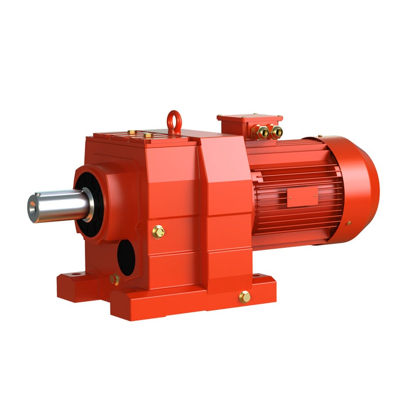
| سلسلة WR | محوري متوازي (محور الإدخال/الإخراج موازٍ) | حتى 18000 نيوتن·متر | ناقلات الحركة، الأسمنت، المطاط، محركات الصناعات الثقيلة |
| سلسلة WF | محور متوازي (إدخال/إخراج مُزاح) | حتى 18000 نيوتن·متر | التغليف، معالجة الأغذية، أتمتة الصناعات العامة |
| سلسلة WS | تجميع حلزوني-دودي (مرحلتان) | حتى 4200 نيوتن·متر | أتمتة المصنع العامة، الناقلات ذات الحمولة المعتدلة |
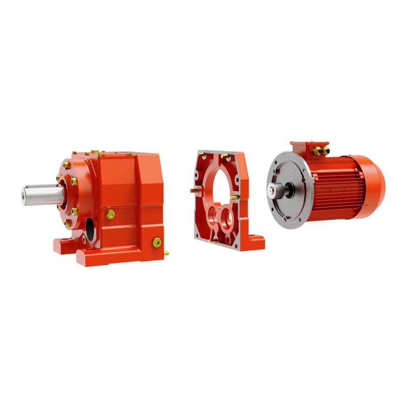
أبعاد غلاف سلسلتي WR وWF متوافقة مع موديلات SEW، مما يتيح التركيب والاستبدال المباشر للمعدات الحالية دون الحاجة إلى تعديلات هيكلية.
FAQ: الترابيس الحلزونية مقابل الترابيس المستقيمة
ما الفرق بين الترابيس الحلزونية والترابيس المستقيمة؟
الترابيس المستقيمة تحتوي على أسنان مستقيمة تتلامس فجأة عبر عرض السن بالكامل، مما يولد ضوضاء تأثيرية وتتركز الإجهادات. أما الترابيس الحلزونية فلها أسنان مائلة تتلامس تدريجياً، مع بقاء عدة أسنان في حالة تلامس في نفس الوقت لنقل الطاقة بسلاسة وهدوء وكفاءة أعلى.
لماذا تستخدم علب التروس عالية الجودة دائماً الترابيس الحلزونية؟
توفر الترابيس الحلزونية نسبة تلامس أعلى، وضوضاء أقل، وقدرة تحمل أكبر للحمل بالنسبة لوحدة الحجم، وعمر خدمة أطول — مما يجعلها المعيار الهندسي لعلب نقل الحركة في السيارات، والمصاعد، وعلب التروس الصناعية، وأي تطبيق تكون فيه الموثوقية والتشغيل الهادئ أمراً لا غنى عنه.
ما هي مشكلة القوة المحورية في التروس الحلزونية وكيف تُحل؟
تولّد هندسة الأسنان المائلة قوة محورية على طول العمود. وتتعامل شركة ووما درايف مع هذه القوة باستخدام محامل تماس زاويّة أو محامل دفع عند نهايتي العمود، ما يمتص الأحمال المحورية بالكامل دون المساس بتوزيع الحمل على وجه الترس أو كفاءته.
متى يجب استخدام التروس المستقيمة بدلًا من التروس الحلزونية؟
تُستخدم التروس المستقيمة في التطبيقات ذات السرعة المنخفضة أو الحمولة المنخفضة أو التي تراعي التكلفة، حيث يكون مستوى الضوضاء مقبولًا ولا يمكن التحميل المحوري على العمود. أما في أي نظام تشغيل صناعي مستمر، فإن التروس الحلزونية تُعد الخيار الأمثل من حيث الأداء والتكلفة الإجمالية للملكية.
أي سلسلة من علب التروس التابعة لشركة ووما درايف تستخدم التروس الحلزونية؟
جميع سلاسل WK (زاوية قائمة مكوّنة من تروس مخروطية وحلزونية)، وWR (محورية متوازية مع المحور)، وWF (محاذاة متوازية)، وWS (تركيبة تروس حلزونية ومسمارية) تستخدم تروسًا حلزونية دقيقة كمعيارٍ أساسي، وتصل كفاءتها إلى ٩٤–٩٨٪ مع تشغيلٍ هادئ في مختلف التطبيقات الصناعية.
تستطيع التروس المستقيمة التشغيل. أما التروس الحلزونية فتشتغل لفترة أطول، وباستقرارٍ أكبر، وهدوءٍ أكثر — وفي التطبيقات الصناعية التي تهم فيها أوقات التوقف عن العمل، والضوضاء، وكفاءة استهلاك الطاقة، يكون الاختيار واضحًا.
هل ترغب في معرفة أي سلسلة من علب التروس الحلزونية تناسب تطبيقك؟
 أخبار عاجلة