
 EN

1. Step 1: Define Your Application Conditions & Duty Cycle
Selecting an industrial speed reducer begins with the mechanics of the driven machine, not catalog parameters. A speed reducer serves two simultaneous functions: rotational speed reduction and mechanical torque multiplication. Prioritizing one without understanding application dynamics leads to premature gear tooth pitting or motor thermal overload.
Load Classification
- Uniform Load (fB = 1.0–1.2): Centrifugal pumps, liquid agitators, steady-speed belt conveyors. Minimal dynamic inertia.
- Moderate Shock (fB = 1.3–1.6): Food packaging lines, rotary kilns, industrial mixers with variable viscosity.
- Heavy Shock (fB = 1.8–2.5+): Stone crushers, metal stamping presses, bucket elevators, reciprocating feeders.
Duty Schedule & Thermal Limits
- Continuous Duty (S1): 24-hour non-stop running. Governed primarily by thermal power dissipation limits rather than mechanical strength.
- Intermittent Duty (S3/S5): Frequent start-stop cycles impose peak acceleration torque (up to 200–300% of nominal rating).
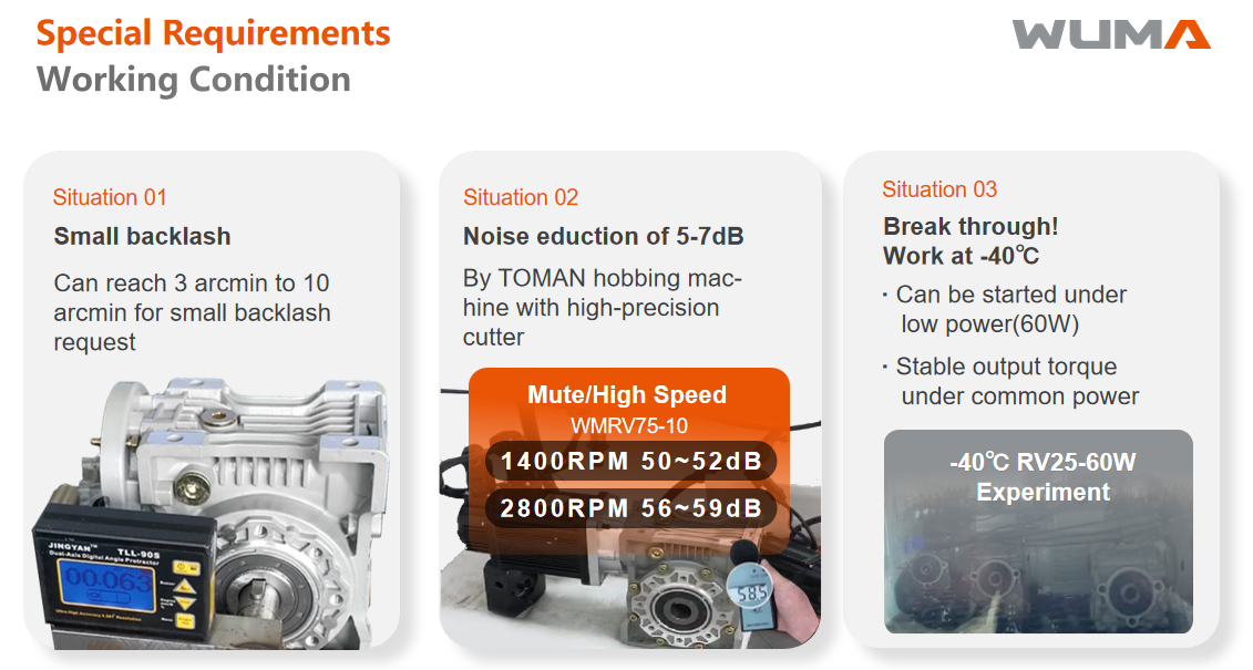
- Ambient Range: Extreme ambient temperatures (<-10°C or >40°C) necessitate synthetic lubricants and specialized FKM seals.
2. Step 2: Determine Speed, Torque & Safety Margin (Three Practical Rules of Thumb)
You do not need an engineering handbook or complicated formulas to size a gearbox accurately. In practice, seasoned maintenance engineers rely on three straightforward rules of thumb:
Rule 1: How Much Do You Need to Slow Down? (Speed Ratio)
Standard industrial AC electric motors spin fast—typically around 1450 rpm (at 50 Hz) or 1750 rpm (at 60 Hz). However, a conveyor belt or mixer drum may only need to turn at 29 rpm.
The practical check: Simply divide the motor's speed by your target machine speed: 1450 ÷ 29 = 50. That tells you that you need a 50:1 reduction ratio. The gearbox will step the rotation down by 50 times.
Rule 2: How Much Real Muscle Does the Machine Need? (Output Torque)
Motor horsepower (kW) tells you how much electricity the motor consumes, but torque (Nm) is the actual twisting force that moves your load. Think of a gearbox as a mechanical lever:
Every time you cut the speed in half, the available twisting force nearly doubles. When you slow the speed down by 50 times, the output shaft delivers immense muscle. Instead of calculating torque by hand, look up your target ratio in the gearbox catalog table: verify that the model's rated output torque (Nm) comfortably exceeds the peak resistance force required to move your product.
Rule 3: Always Add a Safety Buffer (Service Factor)
Never size a gearbox to match your exact working load. When a motor kicks on, or when raw material suddenly jams in a conveyor, the peak shock can momentarily hit 200% to 300% of normal running force.
The rule of thumb:
• Smooth, continuous work (e.g., light belt conveyor, fan): Add a 20% to 25% safety buffer (select a gearbox rated at 1.2× your normal requirement).
• Frequent stops, starts, or mixing thicker liquids: Add a 40% to 60% buffer (1.4× to 1.6×).
• Heavy impacts, crushing, or sudden jamming: Add an 80% to 150% buffer (1.8× to 2.5×) to guarantee the gear teeth never strip.
3. Step 3: Gear Architecture Selection & Engineering Decision Matrix
Industrial gearboxes utilize distinct gearing geometries. Selecting between worm, helical, hypoid, or stainless steel models depends on your efficiency targets, spatial layout, and environmental demands:
| Gearbox Architecture | WUMA Series | Efficiency Range | Primary Mechanical Merits | Best-Fit Applications |
|---|---|---|---|---|
| Worm Gearbox | WMRV Series | 60% – 88% | Compact 90° right-angle layout; reliable static self-locking (i > 60); low initial cost. | Belt conveyors, automated doors, indexing lifts. |
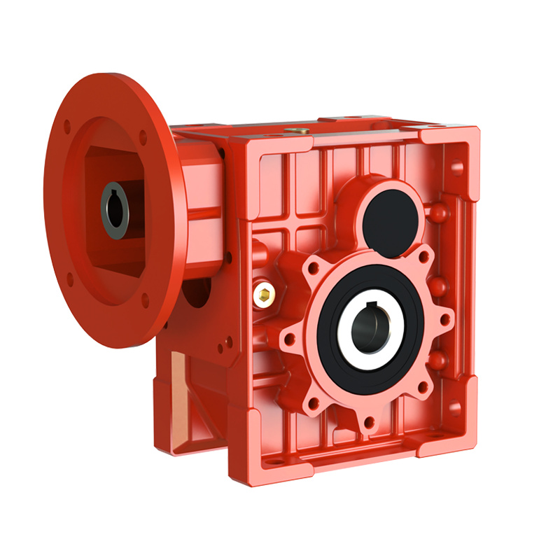
| Hypoid Reducer | WKM Series | 90% – 94% | Direct drop-in replacement for WMRV dimensions; double the operating life; lower heat generation. | Packaging lines, robotics, continuous logistics. |
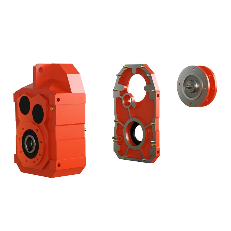
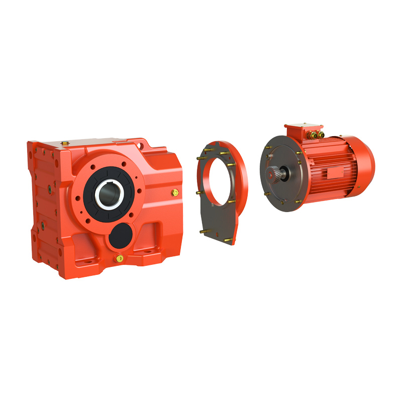
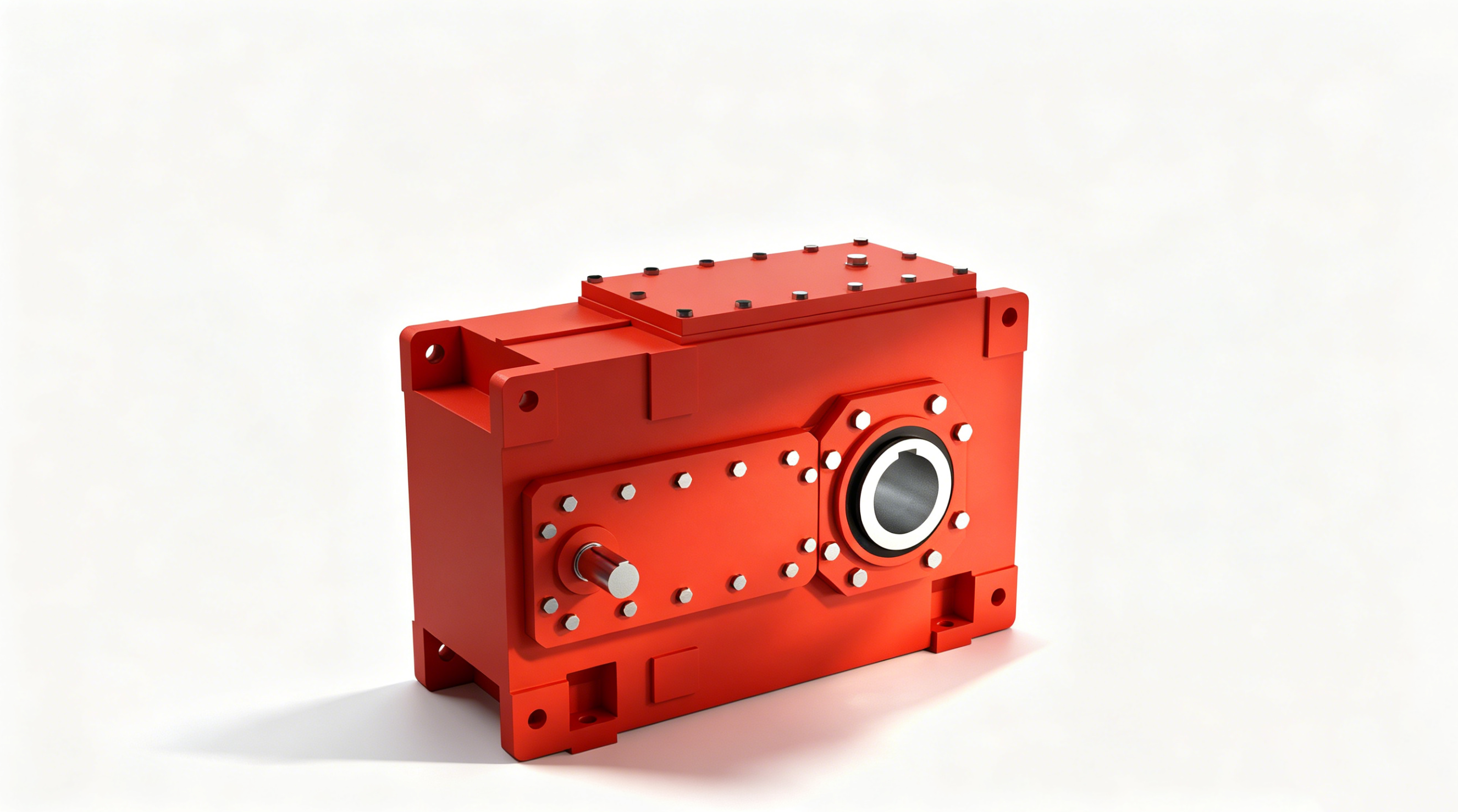
| Helical Gearbox | WR / WF / WK / WS | 94% – 98% | Heavy torque capacity (up to 18,000 Nm); continuous high-efficiency rolling contact. | Heavy industrial conveyors, mining, wastewater. |
| Stainless Steel Unit | WMSS / SSVF | 80% – 92% | SUS304/316 smooth cast housing; IP69K washdown; zero-crevice hygienic design. | Food processing, pharmaceutical, chemical brewing. |
4. Step 4: Mechanical Interface & Mounting Configurations
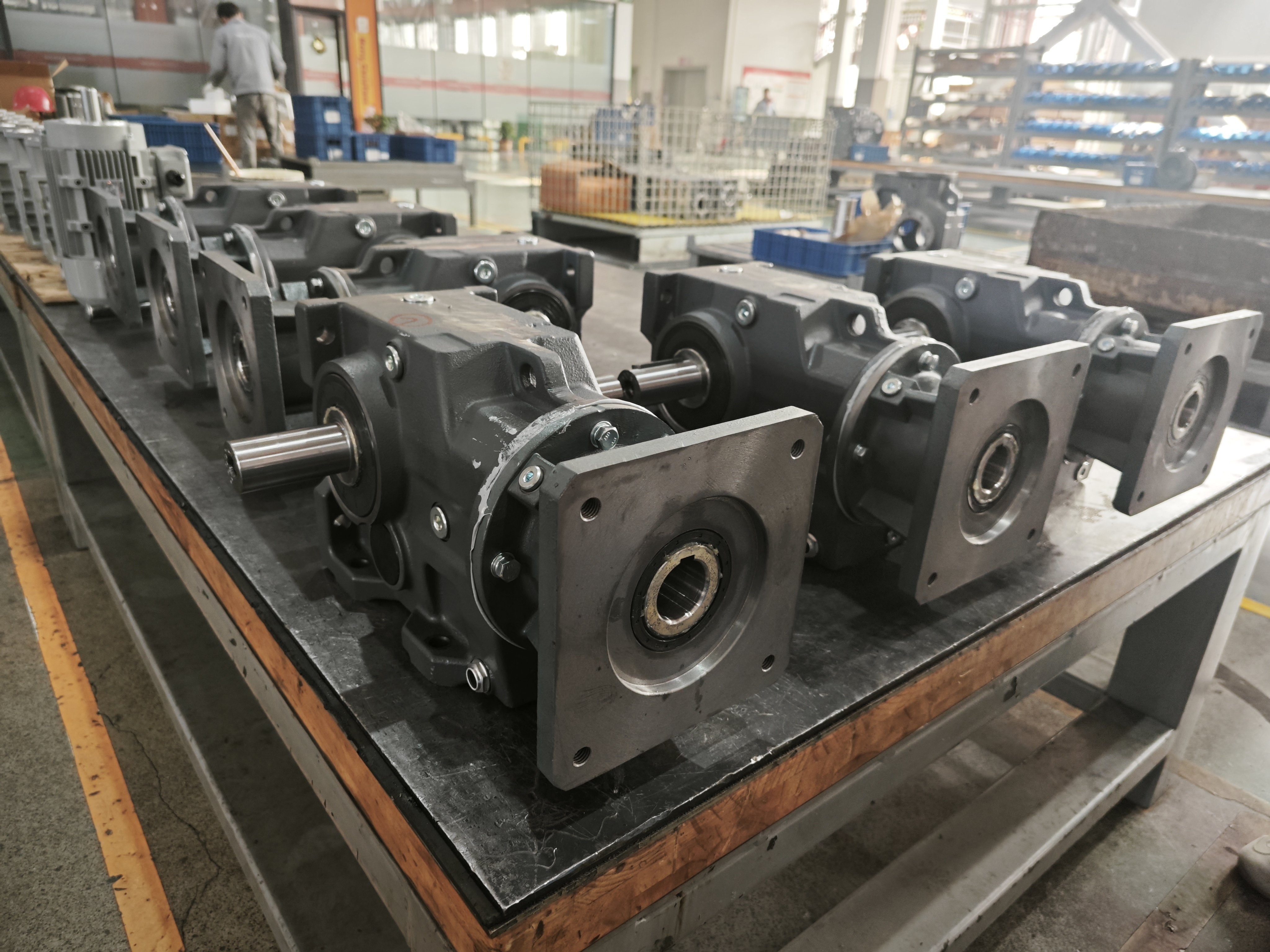
Mechanical compatibility guarantees vibration-free operation and easy plant maintenance. Confirm spatial constraints and shaft coupling types early in design:
Output Connection Styles
Hollow Bore Shaft: Direct slip-on shaft mounting with torque arm; eliminates flexible couplings and alignment procedures.
Solid Output Shaft: Single or dual extension for sprockets, pulleys, or rigid couplings.
Output Flange (FA/FB): Rigid face-mounting onto machine sidewalls.
Input Interface Styles
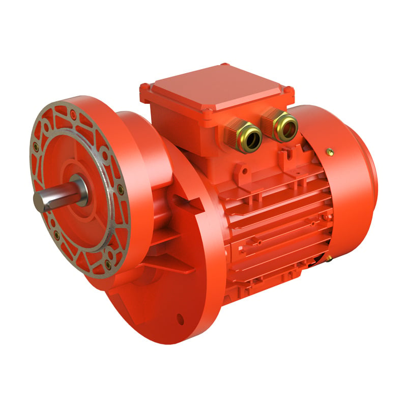
IEC / NEMA Motor Flange: Standardized direct motor mating with quill or plug-in shaft.
Solid Input Shaft: For external pulley, timing belt, or hydraulic motor inputs.
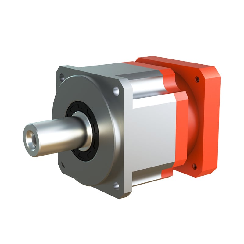
Servo Motor Square Flange: High-precision input clamping for automated motion control.
FR = (2000 × T × fz) / d.5. Step 5: Environmental Ingress, Lubrication & Backlash Tolerance
Long-term operating reliability depends on sealing integrity, appropriate lubrication, and precision grade matching:

- IP Enclosure Standards: Standard indoor machinery requires IP54/IP55. Outdoor, humid, or dusty quarry locations demand IP65/IP66 with double-lip NBR or FKM seals. High-pressure chemical washdowns require IP69K stainless steel housings.
- Lubrication Selection: Smaller aluminum units (e.g., WMRV025–090) come pre-filled with lifelong synthetic polyglycol (PAG) VG320 lubricant, requiring zero oil changes. Large cast iron helical gear units utilize mineral or synthetic gear oils with periodic change intervals (every 10,000 operational hours).
- Backlash Specifications: Standard industrial conveyors accommodate torsional backlash of 10 to 30 arc-minutes. In contrast, precision indexing rotary tables and automated CNC positioning systems require precision servo gearheads with backlash ≤ 1 to 5 arc-minutes.
6. Five Critical Sizing Mistakes That Cause Premature Drivetrain Failure
Mistake 1: Sizing by Motor Horsepower (kW) Instead of Output Torque (Nm)
Motor power does not dictate mechanical holding power. A 1.5 kW motor paired with a 100:1 ratio generates vastly greater torque than the same motor with a 10:1 ratio. The driven load's torque requirement must always serve as the primary sizing benchmark.
Mistake 2: Overlooking Startup Inertia & Shock Factor (fB)
Across-the-line electric motor starts can generate transient peak torques equal to 250% to 350% of full-load running torque. Sizing with fB = 1.0 on a high-inertia load guarantees early shaft fracture or gear tooth shearing.
Mistake 3: Extreme Over-Sizing or Under-Sizing
Under-sizing leads to continuous thermal degradation and gear tooth spalling. Conversely, extreme over-sizing unnecessarily inflates capital costs, adds deadweight, and increases rotational inertia on cyclic servo applications.
Mistake 4: Disregarding Overhung (Radial) and Axial Shaft Loads
Mounting heavy sprockets or pulleys far from the gearbox housing shoulder exerts excessive bending moments on output bearings. Always cross-check catalog allowable overhung load (FR2) tables.
Mistake 5: Neglecting Thermal Power Ratings in Continuous S1 Duty
In continuous duty, worm gearboxes can experience thermal saturation where friction generates heat faster than the housing dissipates it. When thermal power (Pt) is lower than motor mechanical power, auxiliary cooling fans or higher-efficiency helical/hypoid gearboxes must be deployed.
FAQ
How do I calculate the required gear reducer torque from motor power?
Output torque is calculated using the formula: T₂ = (9550 × P₁ × i × η) / n₁, where P₁ is motor power in kW, i is the reduction ratio, η is transmission efficiency (typically 0.65–0.90 for worm, 0.94–0.98 for helical), and n₁ is input speed in rpm. The selection torque must satisfy: T_selected ≥ T₂ × fB, where fB is the operational service factor.
What service factor (fB) should be applied when sizing a gearbox?
For uniform loads running under 8 hours/day (e.g., small belt conveyors or centrifugal pumps), an fB of 1.0 to 1.25 is standard. For moderate shock loads and 16–24 hour continuous duty (mixers, packaging equipment), apply fB = 1.35 to 1.6. Heavy impact loads (crushers, stamping machines, heavy hoists) require fB ≥ 1.8 to 2.5.
When should I choose a hypoid (WKM) or helical reducer over a worm gearbox (WMRV)?
While worm gearboxes (WMRV) offer cost-effective static self-locking (at ratios i > 60) and compact right-angle installation, their sliding contact limits efficiency to 60%–85% at higher ratios. Hypoid reducers (WKM) provide up to 90%–94% efficiency with identical mounting footprints, reducing operating energy costs. For high-torque inline or parallel configurations with continuous duty, helical reducers (WR/WF/WK) deliver >96% efficiency.
Can WUMA customize gearbox mounting dimensions for drop-in replacements?
Yes. Zhejiang Wuma Drive Co., Ltd. provides modular flange interfaces, customized shaft diameters, metric/imperial keyways, and special torque-arm assemblies to achieve direct drop-in replacement for mainstream European and Japanese gearbox brands without modifying existing machinery beds.
Need Application-Specific Gear Reducer Sizing Support?
WUMA application engineers provide complimentary drivetrain calculations, CAD models, and customized drop-in replacement consultations.
 Hot News