
Traditionally, the three main factors for evaluating gear reducer performance are load capacity, fatigue life, and operational accuracy, often neglecting transmission noise. With the successive promulgation of ISO 14000 and ISO 18000 standards, the importance of controlling gear reducer transmission noise has become increasingly apparent. Industrial development and demands place stricter requirements on gear reducer transmission errors and higher demands on noise control.
Currently, the factors contributing to speed reducer gearbox noise can be analyzed from several aspects, including the design, manufacturing, installation, use, and maintenance of internal and external meshing gears.
Design Reasons and Countermeasures
1.Gear Precision Grade Inside the Gear Reducer
When designing gear reducers, designers often consider economic factors and determine the gear precision grade as economically as possible, neglecting that precision grade is a marker of gear noise and backlash. The Gear Manufacturers Association of America (GMA) has determined through extensive gear research that high-precision gears produce significantly less noise than low-precision gears. Therefore, when conditions permit, the gear precision grade should be increased as much as possible to reduce both transmission errors and noise.
2. Gear Width Inside the Reducer
When the reducer's transmission space allows, increasing the gear width can reduce the unit load under constant torque. This reduces tooth deflection, decreases noise excitation, and thus reduces transmission noise. Research by H. Opaz in Germany shows that, at constant torque, a smaller tooth width results in a higher noise curve gradient than a larger tooth width. Increasing the gear width also increases the gear's load-bearing capacity and improves the reducer's torque capacity.
3. Tooth Pitch and Pressure Angle Inside the Reducer
A smaller tooth pitch ensures more teeth are in contact simultaneously, increasing gear overlap, reducing individual gear deflection, lowering transmission noise, and improving transmission accuracy. A smaller pressure angle, due to a larger gear contact angle and lateral overlap ratio, results in lower operating noise and higher accuracy.
4. Selection of Gear Modification Coefficient Inside the Reducer
Correctly and reasonably selecting the modification coefficient can not only adjust the center distance, avoid gear undercut, ensure concentricity, improve gear transmission performance, increase load-bearing capacity, and extend gear life, but also effectively control backlash, temperature rise, and noise. In closed gear drives, for gears with hardened tooth surfaces (hardness: 350 HBS), the main failure mode is tooth root fatigue fracture. This type of gear drive design is generally based on bending fatigue strength; when selecting the displacement coefficient, it should be ensured that the meshing teeth have equal bending strength. For gears with soft tooth surfaces (hardness <350 HBS), the main failure mode is fatigue pitting. This type of gear drive design is generally based on contact fatigue strength; when selecting the displacement coefficient, it should ensure the highest possible contact fatigue strength and fatigue life.
The constraints for reasonably selecting the displacement coefficient are:
(1) Ensure that the gear being cut does not undercut;
(2) Ensure the smoothness of gear transmission; the overlap ratio must be greater than 1, generally greater than 1.2;
(3) Ensure that the tooth tip has a certain thickness;
(4) When a pair of gears mesh, if the involute of the tooth tip of one gear contacts the transition curve of the tooth root of the other gear, since the transition curve is not an involute, the common normal of the two tooth profiles at the contact point cannot pass through a fixed node, thus causing a change in the transmission ratio and possibly causing the two gears to jam. This "transition curve interference" must be avoided when selecting the displacement coefficient.
5. Gear tooth profile trimming (edge trimming and root trimming) and tooth tip chamfering inside the reducer
The tooth profile at the tooth tip is cut into a slightly convex shape than the correct involute curve. When the gear tooth surface is deformed by external force, it can avoid interference with the meshing gear, reduce noise, and extend gear life. It is important to note that excessive trimming should be avoided, as excessive trimming increases tooth profile error and will have an adverse effect on meshing.
6. Gear Sound Radiation Characteristics Analysis
When selecting gears with different structural forms, a sound radiation model is established for the specific structure, and dynamic analysis is performed to pre-assess the noise of the gear transmission system. This allows for the selection based on different user requirements (usage location, whether unattended, whether in urban areas, specific requirements for above-ground or underground buildings, noise protection requirements, or no other specific requirements).
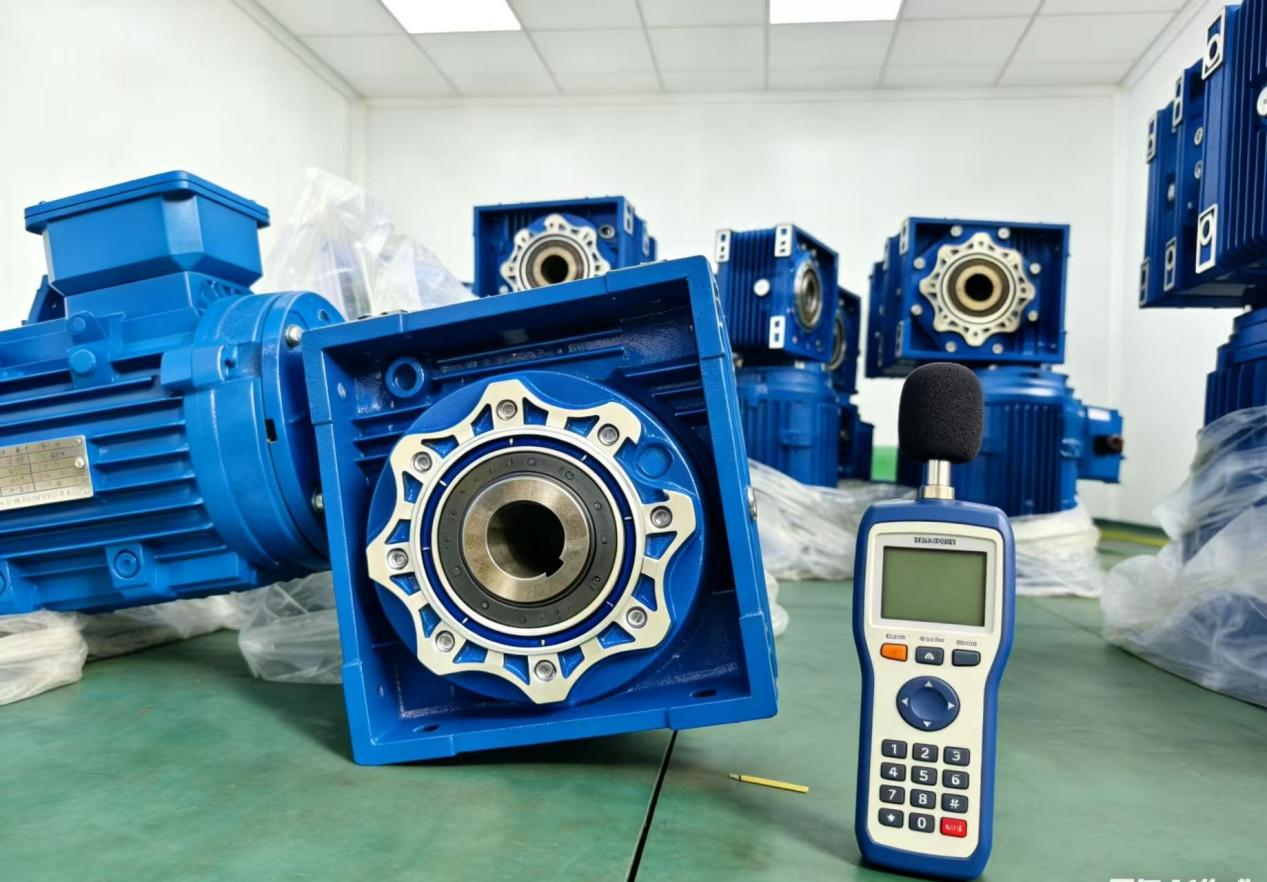
7. Gear Reducer Power Source Operating Speed
Tests on the gear reducer under different speed conditions show that noise increases with the increase of the gear reducer's input speed.
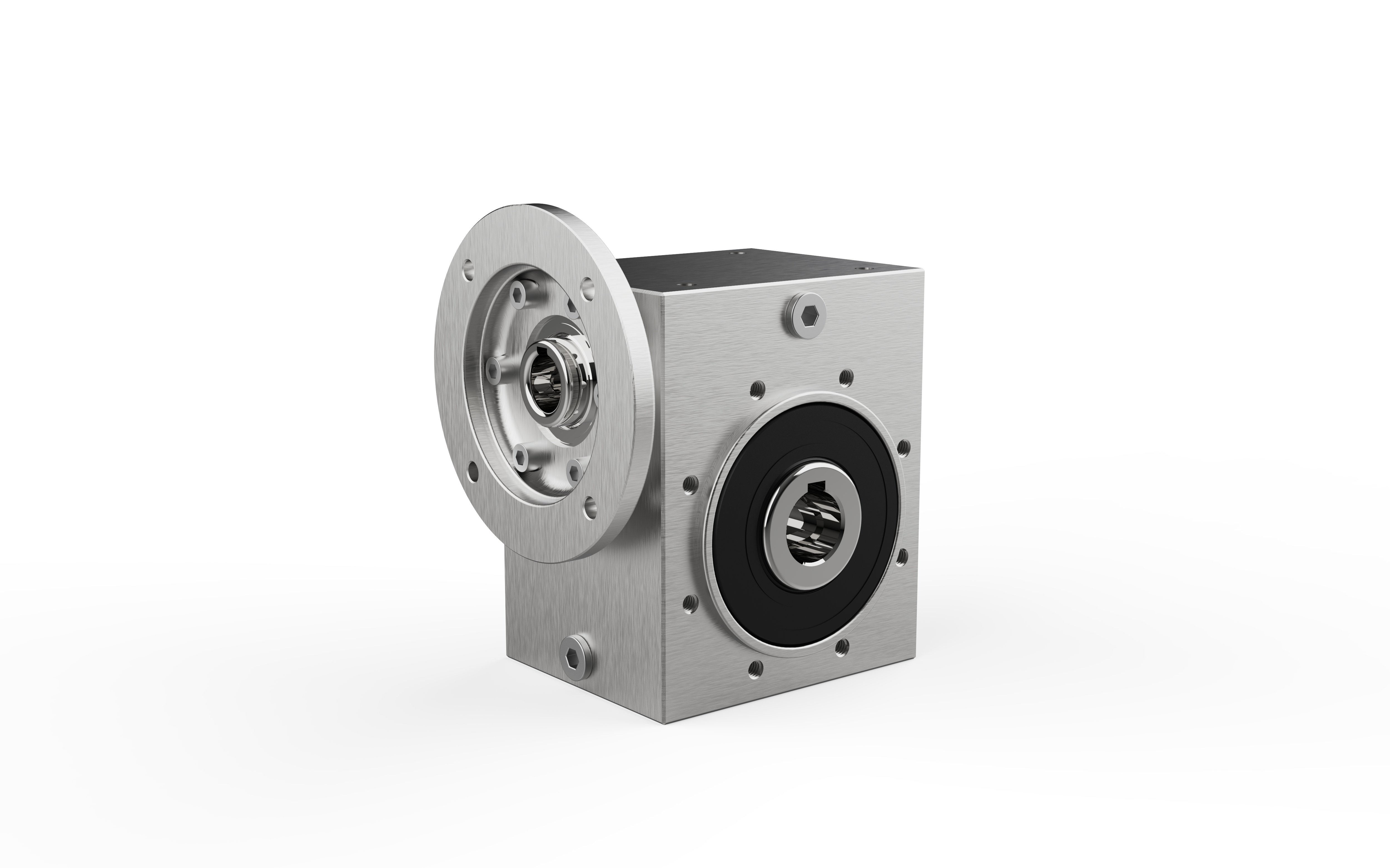
8. Gearbox Housing Structure
Experimental studies show that using a cylindrical housing is beneficial for vibration reduction. Under the same conditions, a cylindrical housing has an average noise level 5dB lower than other types of housings. Resonance testing of the gear reducer housing is conducted to identify resonance locations. Adding appropriate ribs (plates) can improve the housing's rigidity, reduce vibration, and achieve noise reduction. For multi-stage transmissions, the instantaneous transmission ratio change should be minimized to ensure smooth transmission, low impact and vibration, and low noise.
Manufacturing Causes and Countermeasures
1. Influence of Internal Gear Errors in the Reducer
Gear manufacturing errors, including tooth profile error, base pitch deviation, tooth direction error, and radial runout error of the gear ring, are the main errors causing noise in planetary reducer transmissions. These are also key factors in controlling the transmission efficiency of planetary reducers. We will now briefly explain tooth profile error and tooth direction error.
Gears with small tooth profile errors and small tooth surface roughness have noise levels 10 dB lower than ordinary gears under the same test conditions. Gears with small tooth pitch errors have noise levels 6–12 dB lower than ordinary gears under the same test conditions. However, if tooth pitch error exists, the impact of load on gear noise will be reduced.
Tooth direction error will cause the transmission power to not be transmitted across the entire tooth width. The contact area will be directed to one end face or another of the tooth. Due to increased local stress, the tooth will deflect, leading to an increase in noise level. However, under high loads, tooth deformation can partially compensate for tooth direction error.
2. Assembly Concentricity and Dynamic Balance
Misalignment during assembly will lead to imbalance in the shaft system, and the uneven meshing of gears (one side loose, one side tight) will further exacerbate noise. Imbalance during the assembly of high-precision gear drives will severely affect the accuracy of the transmission system.
3. Gear Surface Hardness Inside the Reducer
With the development of gear hardening technology, the high load-bearing capacity, small size, light weight, and high transmission accuracy of gears have led to their increasingly wide application. However, the carburizing and hardening process used to obtain hardened tooth surfaces causes gear deformation, resulting in increased gear transmission noise and shortened lifespan. To reduce noise, the tooth surface needs to be precision machined. Currently, in addition to traditional gear grinding methods, a hardened tooth surface scraping method has been developed. This method reduces gear engagement and disengagement impact by modifying the tooth tip and root, or by reducing the tooth profile of both the driving and driven gears, thereby reducing gear transmission noise.
4. Gearbox System Performance Verification
The machining accuracy of components and the selection method for components before assembly (complete interchangeability, group selection, single-piece selection, etc.) will affect the accuracy level of the assembled system, and its noise level is also within the scope of influence. Therefore, verifying (or calibrating) various system indicators after assembly is crucial for controlling system noise.
Installation Causes and Countermeasures
1.Vibration Reduction and Interception Measures
During gearbox installation, resonance between the gearbox body and the foundation support and connecting parts should be avoided as much as possible to prevent noise generation. Resonance often occurs in one or more gears within the gearbox within certain speed ranges. Besides design reasons, this is directly related to the failure to identify the resonance location during no-load testing and to take corresponding vibration reduction or isolation measures. For some gearboxes requiring low transmission noise and vibration, high-toughness, high-damping foundation materials should be selected to reduce noise and vibration.
2. Component Geometric Accuracy Adjustment
If the geometric accuracy does not meet the standard requirements during installation, resonance of gearbox components may occur, resulting in noise. This is directly related to improving the installation process, increasing tooling, and ensuring the overall quality of assembly personnel.
3. Loose Components
During installation, loosening of individual components (such as bearing preload mechanisms, shaft positioning mechanisms, etc.) can lead to inaccurate system positioning, abnormal meshing, shaft movement, and vibration and noise. This requires a structural design approach to ensure stable connections between mechanisms and to utilize multiple connection methods.
4. Damaged Transmission Components
Improper operation during installation can damage transmission components, leading to inaccurate or unstable system movement; damage to high-speed moving parts can cause oil film vibration; human error can cause dynamic imbalance in moving parts; all of these generate vibration and noise. These causes must be carefully considered and avoided during installation. Damaged components that cannot be repaired must be replaced to ensure a stable noise level for the system.
Reasons and Countermeasures for Use and Maintenance
While proper use and maintenance of the reducer cannot reduce the system noise level or guarantee transmission accuracy, it can prevent performance degradation and extend service life.
1.Internal Cleaning
The cleanliness of the reducer's internal parts is fundamental to its normal operation. The entry of any impurities or contaminants will affect and damage the transmission system, leading to noise generation.
2. Operating Temperature
Ensure the reducer operates at its normal temperature to prevent deformation of components due to excessive temperature rise, ensure proper gear meshing, and thus prevent increased noise.
3. Timely Lubrication and Correct Oil Use
Improper lubrication and incorrect use of lubricating grease will cause immeasurable damage to the reducer. At high speeds, gear tooth surface friction generates a large amount of heat. Improper lubrication will lead to gear tooth damage, affecting accuracy and increasing noise. The design requires appropriate clearance in the gear pair (the clearance between the non-working surfaces of the meshing teeth to compensate for thermal deformation and store lubricating grease). Correct use and selection of lubricating grease can ensure safe and effective system operation, slow down degradation, and stabilize noise levels.
4. Correct Use of the Reducer
Correct use of the reducer can minimize damage to components and ensure a stable noise level. Reducer noise increases with load, so it should be used within the normal load range.
5. Regular Maintenance and Upkeep
Regular maintenance (oil changes, replacement of worn parts, loose fasteners, removal of internal debris, adjustment of component clearances to standard values, and verification of geometric accuracy, etc.) can improve the reducer's resistance to noise level degradation and maintain stable operating conditions.
Reducer transmission noise control is a systematic project involving the entire process of transmission system (gears, housing, connecting parts, bearings, etc.) design, manufacturing, installation, use, maintenance, and even replacement. It places numerous demands not only on designers and manufacturers but also on installers, users, and maintenance personnel. If any of these aspects are not effectively controlled, gear transmission noise control will fail.
 Hot News
2026-06-29
2026-06-24
2026-06-24
2026-06-23
2026-06-18
2026-05-22
Welcome to Wuma , a manufacturer committed to developing and manufacturing various types of gear reducers and gearmotors for the field of gear transmission.
No. 10, Xiangcun Industrial Zone, Dongyuan Town, Qingtian County, Lishui City, Zhejiang, China
Copyright © Zhejiang Wuma Drive Co., Ltd All Rights Reserved Privacy Policy Blog